
Liquid crystal on silicon (LCOS) microdisplay with retarder that reduces light beam polarization changes

Inactive Publication Date: 2006-03-30
INTEL CORP
View PDF13 Cites 30 Cited by
  • Summary
  • Abstract
  • Description
  • Claims
  • Application Information

AI Technical Summary

Problems solved by technology

Traditional liquid crystal on silicon (LCOS)-based displays have limitations, however.

Method used


Image

  • Liquid crystal on silicon (LCOS) microdisplay with retarder that reduces light beam polarization changes
  • Liquid crystal on silicon (LCOS) microdisplay with retarder that reduces light beam polarization changes
  • Liquid crystal on silicon (LCOS) microdisplay with retarder that reduces light beam polarization changes

Examples


Embodiment Construction

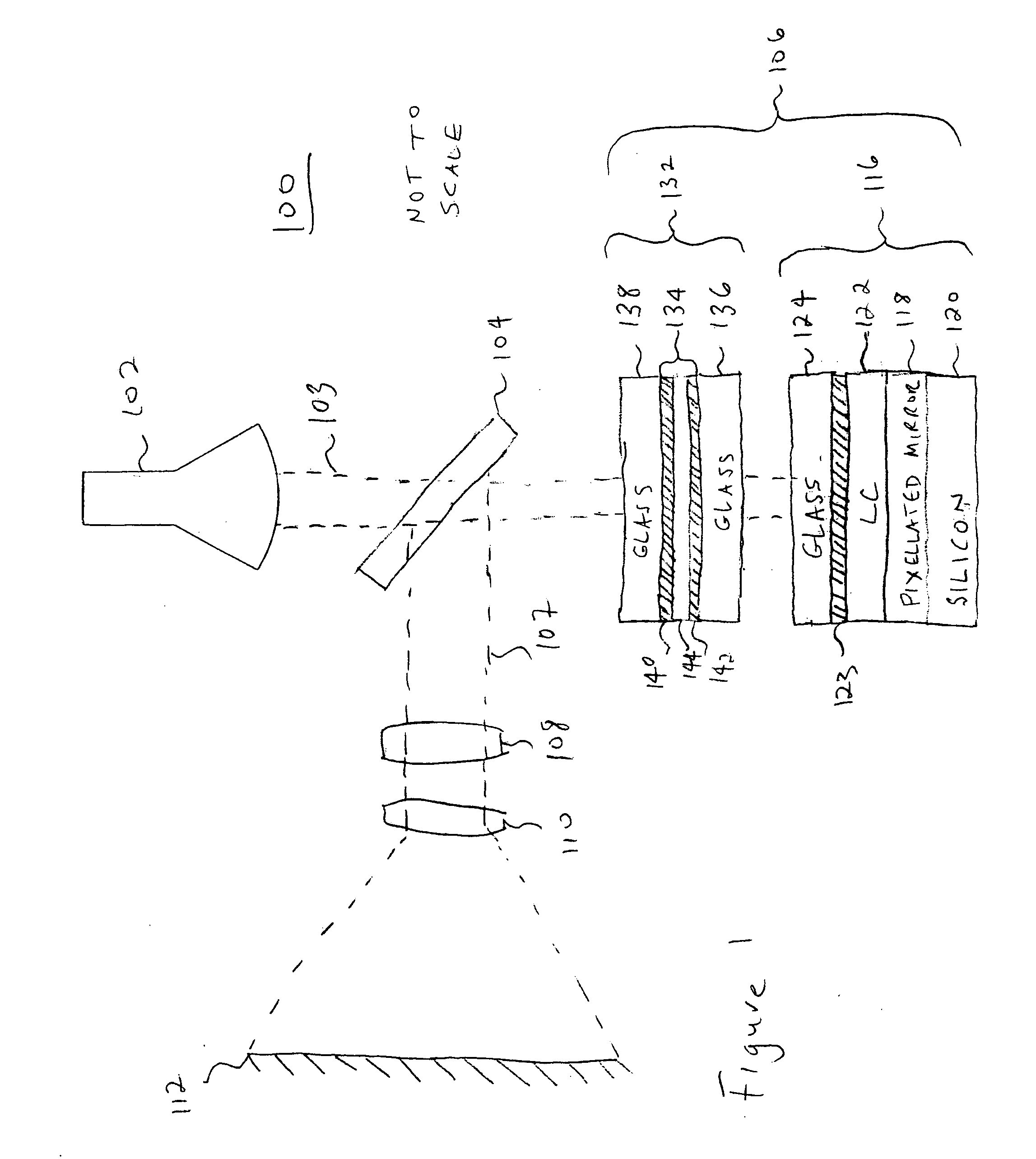
[0015]FIG. 1 is a high-level block diagram of a display system 100 according to an embodiment of the present invention. In the illustrated embodiment, the display system 100 includes a light source 102 operationally coupled to optics 104, such as a broadband or narrow band polarization beam splitter, for example (beam splitter 104). In the illustrated embodiment, the beam splitter 104 is operationally coupled to a light engine 106, to two lenses 108 and 110, and to a screen 112. In embodiments of the present invention, the display system 100 also may include other optics such as homogenizers, color wheels, filters (such as dielectric filters, ultraviolet filters, infrared filters, yellow notch filters, for example), polarization conversion systems, and the like. For purposes of clarity, the optics are not illustrated in the FIG. 1.

[0016] The example light source 102 may be any suitable light source that may emit a light beam 103 having a predetermined polarization state, such as ho...


PUM


Abstract

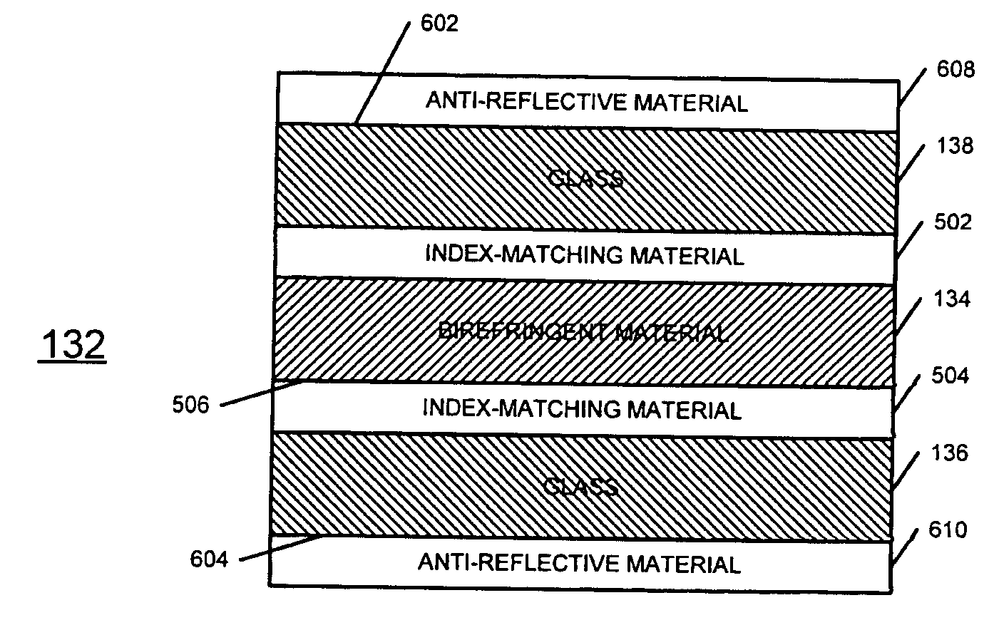
According to embodiments of the present invention, a retarder for a liquid crystal on silicon microdisplay cell may include a twisted nematic cell sandwiched between index of refraction matching layers, isotropic material (for example, glass) disposed on the top and bottom index matching layers and antireflective material disposed on the top and bottom isotropic layers. In one embodiment, the retarder includes a fast axis oriented substantially ninety degrees out of phase relative to a fast axis of the residual retardance of the liquid crystal on silicon microdisplay cell.

Description

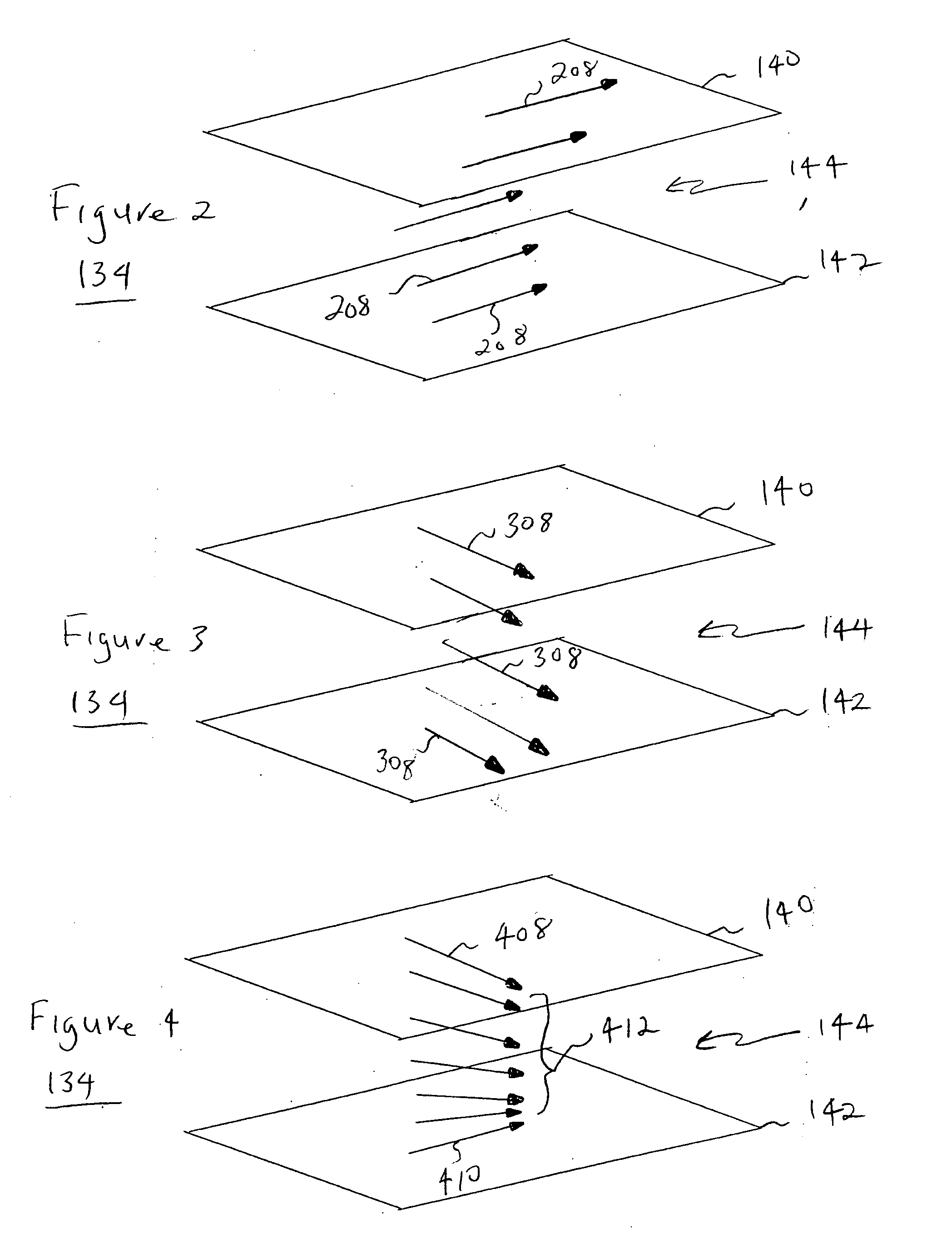
BACKGROUND [0001] 1. Field [0002] Embodiments of the present invention relate to display devices and, in particular, to liquid crystal on silicon (LCOS)-based display devices. [0003] 2. Discussion of Related Art [0004] Liquid crystal on silicon (LCOS)-based displays may be used in rear projection television, front projection television, and high-definition televisions, for example, to display video signals. Traditional liquid crystal on silicon (LCOS)-based displays have limitations, however.BRIEF DESCRIPTION OF THE DRAWINGS [0005] In the drawings, like reference numbers generally indicate identical, functionally similar, and / or structurally equivalent elements. The drawing in which an element first appears is indicated by the leftmost digit(s) in the reference number, in which: [0006]FIG. 1 is a high-level block diagram of a display system according to an embodiment of the present invention; [0007]FIG. 2 is a cross sectional view of a retarder according to an embodiment of the pres...

Claims


Application Information

Patent Timeline
IPC IPC(8): C09K19/02
CPCG02F1/13363G02F1/136277H04N9/3167G02F2413/15G02F2001/133633G02F1/133633
Inventor GRUNNET-JEPSEN, ANDERSWALKER, CHANDA B.MORLEY, ROLAND M.
Owner INTEL CORP
Learn More