Exposure apparatus, and device manufacturing method

a technology of equipment and manufacturing method, applied in the direction of lighting and heating equipment, printing, instruments, etc., can solve the problems of large heat, large power of hg lamps currently used as light sources, and high exhaust gas discharge into the clean room environmen

Inactive Publication Date: 2006-03-30
CANON KK
View PDF5 Cites 3 Cited by
  • Summary
  • Abstract
  • Description
  • Claims
  • Application Information

AI Technical Summary

Benefits of technology

[0007] It is another object of the present invention to provide a unique and improved exposure apparatus and / or an exposure method by which at least one of the inconveniences described above can be removed or reduced.

Problems solved by technology

However, Hg lamps currently used as a light source have a large power of more than 4 kW, and they produce a large heat.
Discharging such high-temperature exhaust gas into a clean room environment would be very undesirable since it burdens a heavy load in respect to the factory equipment.

Method used


Image

  • Exposure apparatus, and device manufacturing method
  • Exposure apparatus, and device manufacturing method
  • Exposure apparatus, and device manufacturing method

Examples


first embodiment

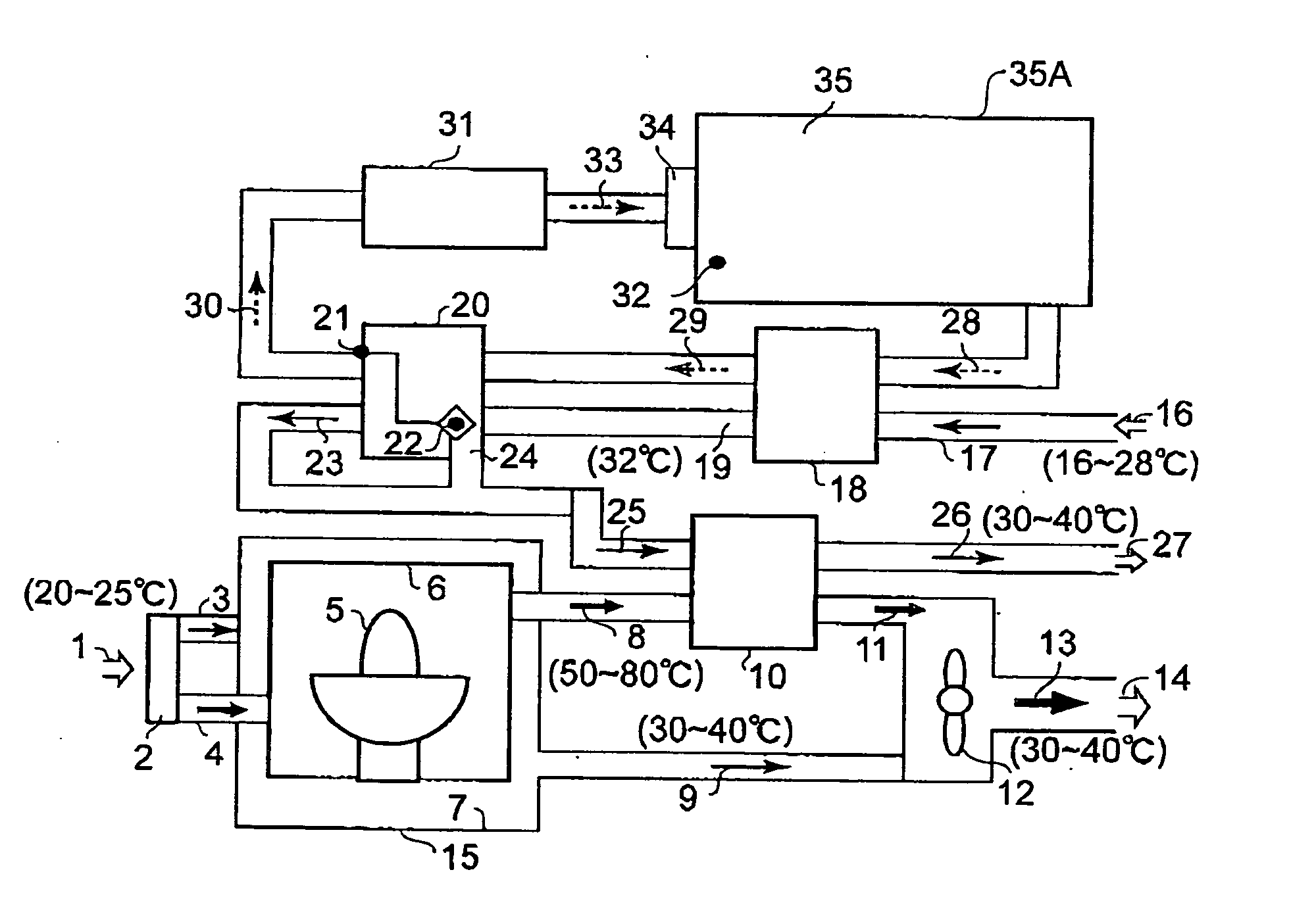
[0017]FIG. 1 is a schematic and diagrammatic view of a general structure of a heat treatment system in a semiconductor exposure apparatus according to a first embodiment of the present invention. Details of the heat treatment system of the semiconductor exposure apparatus according to the first embodiment of the present invention will be explained with reference to FIG. 1.

[0018] Denoted in the drawing at 1 is an outside air to be introduced from the outside to the inside of the apparatus as a cooling air of about 20 to 25° C. Denoted at 2 is an air filter, and denoted at 3 and 4 are outside air introducing paths, respectively. The outside air introducing path 3 functions to introduce the outside air into a lamp box outer shell 7, while the outside air introducing path 4 serves to introduce the outside air into a lamp box inner shell 6. Denoted at 5 is an Hg lamp which is a light source of exposure light, and the temperature thereof becomes very high. The exposure light source 5 is ...

second embodiment

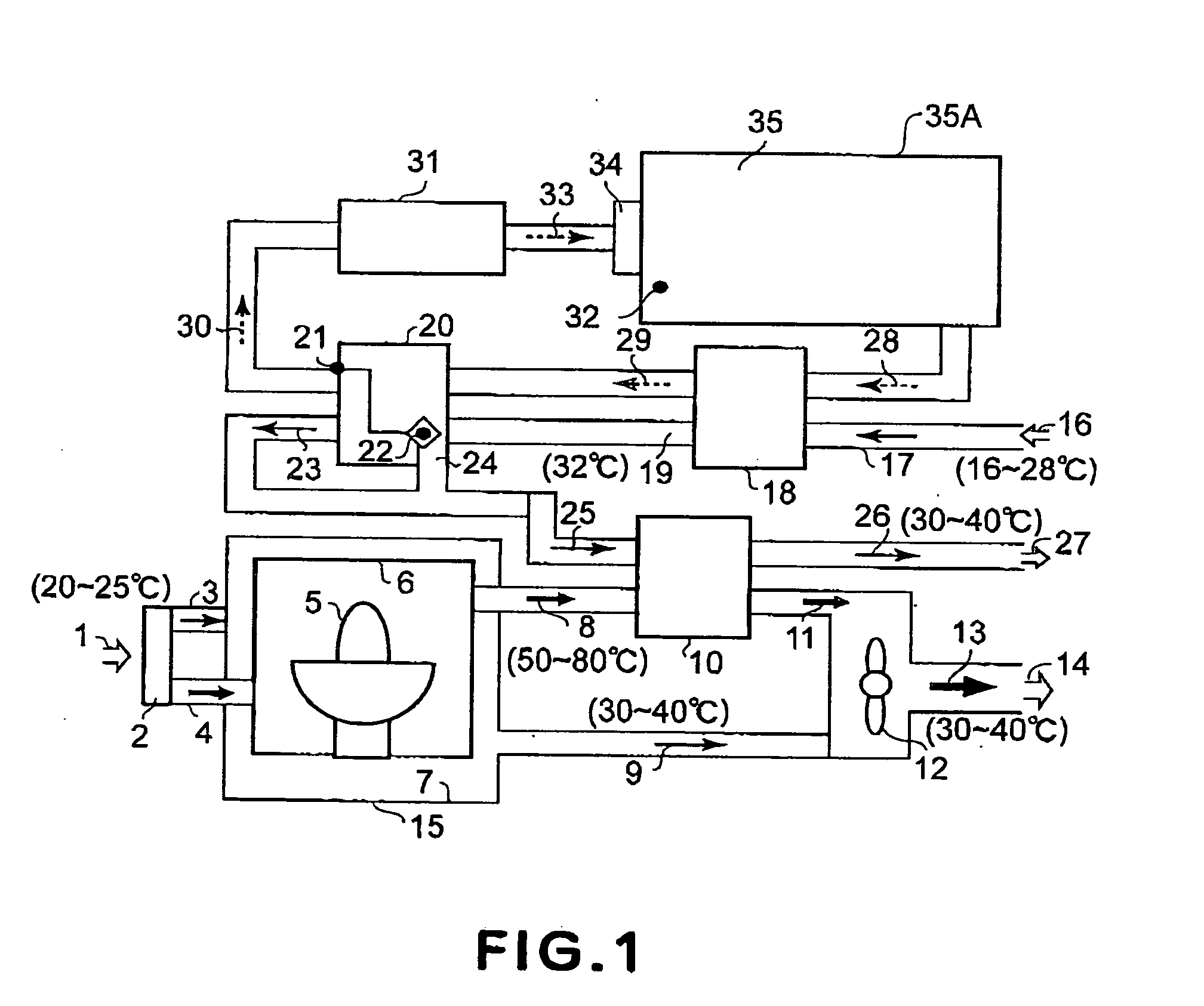
[0022]FIG. 2 is a schematic and diagrammatic view of a general structure of a heat treatment system in a semiconductor exposure apparatus according to a second embodiment of the present invention. Details of the heat treatment system of the semiconductor exposure apparatus according to the second embodiment of the present invention will be explained with reference to FIG. 2.

[0023] In accordance with the embodiment shown in FIG. 2, in addition to the first embodiment, there is a second coarse heating unit 37. The second coarse heating unit 37 uses the ejected water having been heat-exchanged at the heat exchanger 10 to coarsely heat again a portion of the temperature controlling medium 30, having been coarsely heated and temperature-controlled. As a result of this, a temperature controlling medium 39 having been coarsely reheated and having a temperature higher than the temperature controlling medium 30 is produced.

[0024] Subsequently, the temperature controlling media 30 and 39 ar...

third embodiment

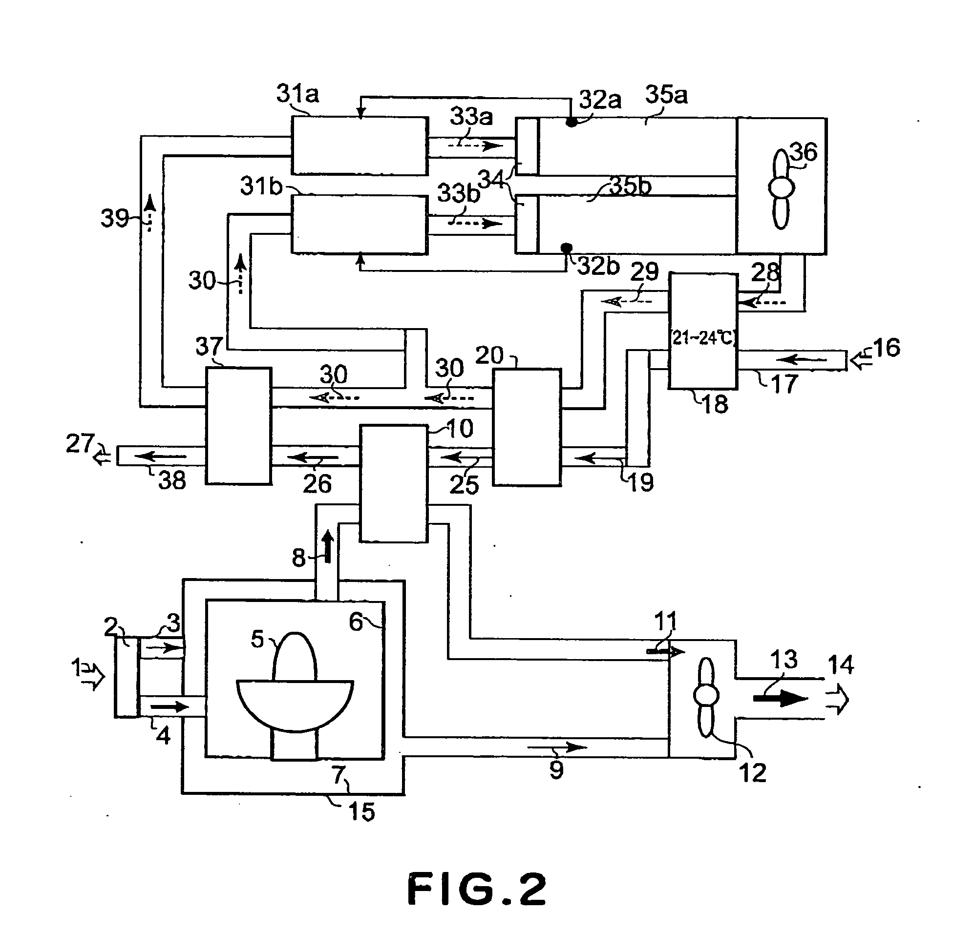
[0025]FIG. 3 is a schematic and diagrammatic view of a general structure of a heat treatment system in a semiconductor exposure apparatus according to a third embodiment of the present invention. Details of the heat treatment system of the semiconductor exposure apparatus according to the third embodiment of the present invention will be explained with reference to FIG. 3.

[0026] In the third embodiment shown in FIG. 3, the temperature controlling medium 39 coarsely reheated in the structure of the second embodiment and the branched temperature controlling medium 30 are mixed with each other by means of the provision of a bypass 40. The mixture of the temperature controlling medium 39 and the temperature controlling-medium 30 provides a temperature controlling medium 41. Here, the temperature of the temperature controlling medium 41 is measured by use of a temperature sensor 42, so that the degree of opening of a two-way control valve (or three-way control valve) 43 is adjusted in a...


PUM


Abstract

Disclosed is an apparatus for exposing a wafer to light, the apparatus including a light source unit having a light source for emitting light, a first cooling unit for cooling the light source unit, the first cooling unit having a gas flowpassage for a gas passing through the light source unit, and a second cooling unit for cooling the gas, the second cooling unit having a first fluid flowpassage for a first fluid which is to be heat-exchanged with the gas in the gas flowpassage at a position downstream of the light source unit with respect to the flow of the gas.

Description

FIELD OF THE INVENTION AND RELATED ART [0001] This invention relates to an exposure apparatus having a light source which is also a heat generation source. [0002] In semiconductor exposure apparatuses, precise temperature control is required to assure precise positioning. The temperature control can be carried out in various ways such as ventilating a heat source by using a gas, precise air-conditioning based on gas circulation, removing heat from the heat source by using a liquid, and precise temperature control of an object by using a liquid. Where the heat source is outside a clean area, as in the case of heat generation from a light source or an electricity rack, an outside air is introduced and the heat is exhausted by using a blower. For temperature stabilization of the space in the clean area, a gas such as air or nitrogen is circulated as a temperature adjusting medium. The circulated and returned gas is heat-exchanged by using cooling water, and it is cooled to a temperatur...

Claims


Application Information

Patent Timeline
Patent Type & Authority Applications(United States)
IPC IPC(8): G03B27/52
CPCG03F7/70858G03F7/70008
Inventor SHIGARAKI, TOSHIYUKI
Owner CANON KK
Why Eureka
Try Eureka