Packet reception control device and method

a control device and packet technology, applied in the field of packet reception control devices and methods, can solve the problems of large amount of unpredictable packets, inability to predict or guarantee the coming reception packets, and inability to add the network interface function to the design of conventional equipment, so as to improve the overload state of the apparatus receiving packets

Inactive Publication Date: 2006-03-30
PANASONIC CORP
View PDF21 Cites 63 Cited by
  • Summary
  • Abstract
  • Description
  • Claims
  • Application Information

AI Technical Summary

Benefits of technology

[0118] As described above, according to the present invention, an overload state of an apparatus receiving packets can be improved. Therefore,

Problems solved by technology

With this tendency, there have emerged problems occurring in adding the network interface function to conventional equipment designs.
The Ethernet is a packet transmission/reception network, in which it is essentially impossible to predict or guarantee coming reception packets.
In another situation, traffic for jeopardizing security such as port scan, denial of service attack and computer virus may arise causing coming of a large amount of unpredictable packets.
In the situations described above, if equipment faces coming of reception packets of an amount exceeding the ability of the equipment, the processor of the equipment is likely to fall in an overload state devoting most of its processing power to processing of the reception packets.
As a result, the e

Method used


Image

  • Packet reception control device and method
  • Packet reception control device and method
  • Packet reception control device and method

Examples


embodiment 1

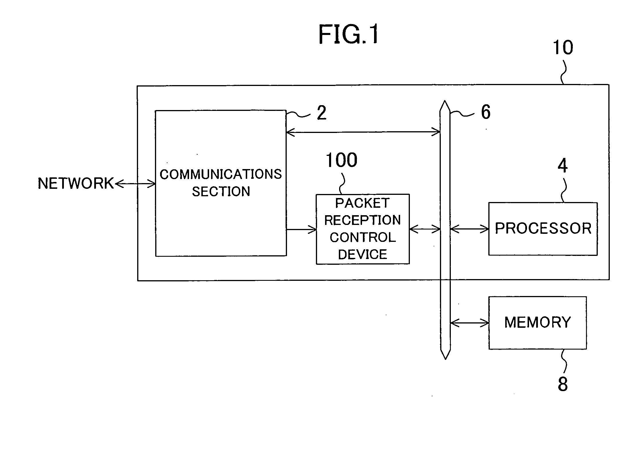
[0143]FIG. 1 is a block diagram of a packet communications system in Embodiment 1 of the present invention. The packet communications system of FIG. 1 includes a memory 8 and a semiconductor integrated circuit 10. The semiconductor integrated circuit 10 includes a communications section 2, a processor 4 and a packet reception control device 100. The processor 4 may be a CPU or a digital signal processor (DSP), for example.

[0144] The communications section 2 transmits / receives packets to / from a network, and outputs received packets (reception packets) to the packet reception control device 100. The communications section 2 also transfers / receives packets and the like to / from the processor 4 and the memory 8 via a bus 6 as required.

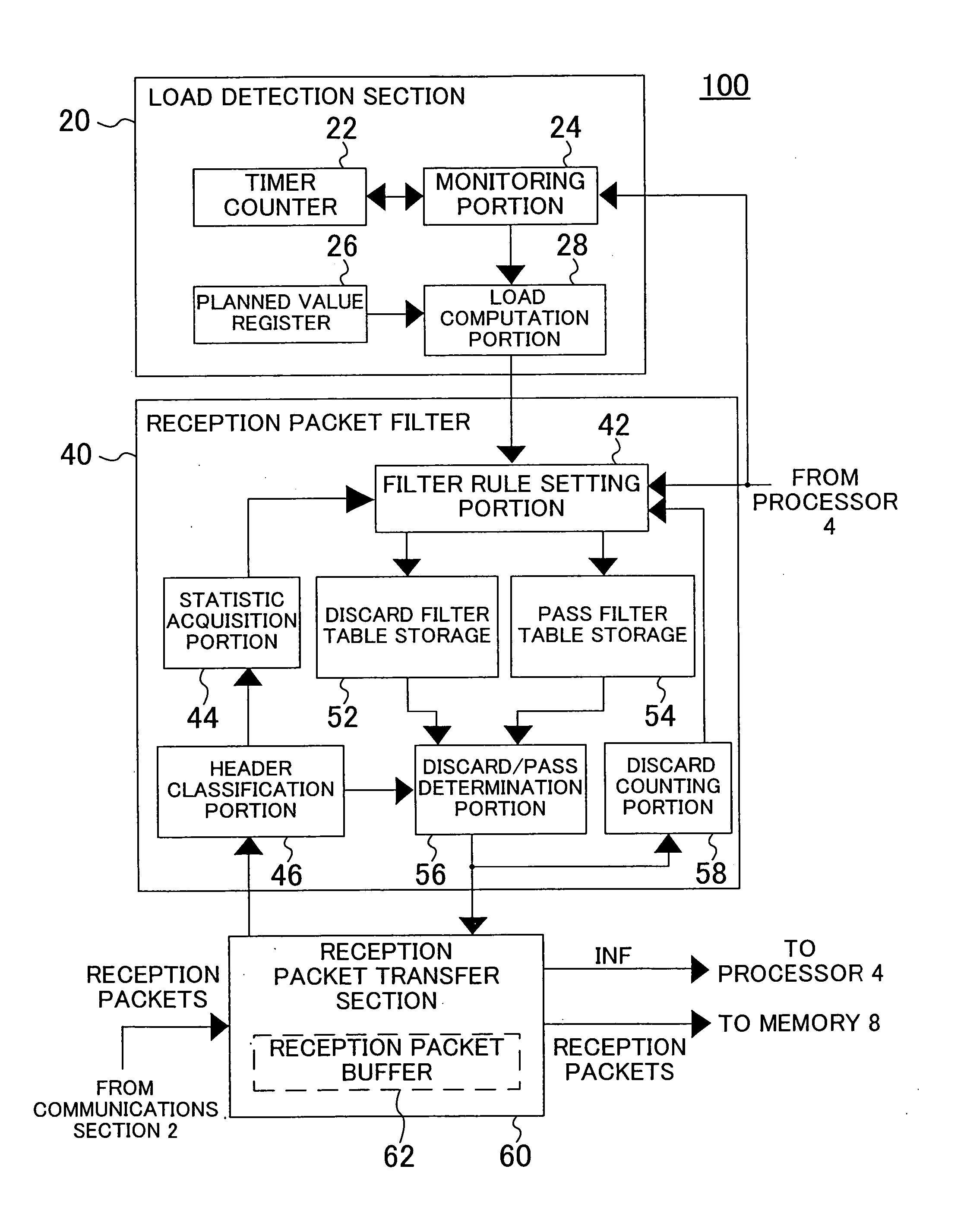
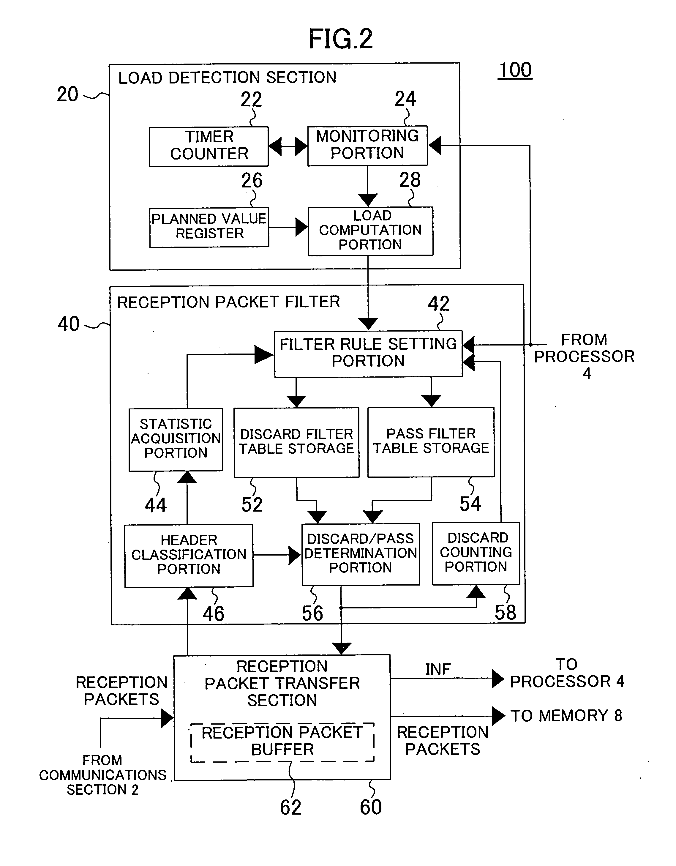
[0145] The packet reception control device 100 outputs packets received from the communications section 2 to the memory 8 via the bus 6. The processor 4 reads packets from the memory 8. The packet reception control device 100 controls such transfer of pac...

embodiment 2

[0172]FIG. 6 is a block diagram of a packet reception control device 200 of Embodiment 2 of the present invention. The packet reception control device 200 of FIG. 6 includes a load detection section 220 and a reception notification section 270 as the reception control section. The packet reception control device 200 is used in place of the packet reception control device 100 in the packet communications system of FIG. 1.

[0173] The load detection section 220 includes a timer counter 222, a monitoring portion 224 and a load computation portion 228. The reception notification section 270 includes an upper limit register 272, a reception notification stop control portion 274 and a counter 276.

[0174] The processor 4 executes a task of accessing the monitoring portion 224. The task is started periodically on a multitask OS by the processor 4. The period of the task is set to be shorter than the timeout of the timer counter 222. The timeout is defined as the time that has elapsed from th...

embodiment 3

[0192]FIG. 7 is a block diagram of a packet reception control device 300 of Embodiment 3 of the present invention. The packet reception control device 300 of FIG. 7 includes a load detection section 320, an overload remedy section 330, a reception packet filter 340 as the reception control section, and a reception packet transfer section 360. The packet reception control device 300 is used in place of the packet reception control device 100 in the packet communications system of FIG. 1.

[0193] The load detection section 320 includes a timer counter 322 and a monitoring portion 324. The overload remedy section 330 includes an overload control portion 332, a counter 334 and a discard counting portion 336. The reception packet filter 340 includes a filter rule setting portion 342, a statistic acquisition portion 344, a header classification portion 346, a discard filter table storage 352, a pass filter table storage 354 and a discard / pass determination portion 356.

[0194] The reception...


PUM


Abstract

The packet reception control device includes: a load detection section for detecting a load on a processor and outputting the detection result; and a reception control section for determining whether or not the processor should receive a reception packet based on the detection result output from the load detection section and outputting the determination result. The processor receives the reception packet according to the determination result output from the reception control section.

Description

CROSS-REFERENCE TO RELATED APPLICATIONS [0001] This application claims priority under 35 U.S.C. § 119 on Patent Applications No. 2004-279981 filed in Japan on Sep. 27, 2004 and No. 2005-264201 filed in Japan on Sep. 12, 2005, the entire contents of which are hereby incorporated by reference. BACKGROUND OF THE INVENTION [0002] The present invention relates to a technology of controlling reception of packets from a network. [0003] The tendency of adding the function of establishing connection with a network such as the Internet to conventionally existing equipment is increasing year by year. With this tendency, there have emerged problems occurring in adding the network interface function to conventional equipment designs. [0004] A representative example of networks is Ethernet conforming to the Institute of Electrical and Electronics Engineers (IEEE) 802.3. The Ethernet is a packet transmission / reception network, in which it is essentially impossible to predict or guarantee coming re...

Claims


Application Information

Patent Timeline
IPC IPC(8): H04L12/26H04L47/20H04L47/32H04L47/76
CPCH04L49/90H04L63/1458H04L49/9078
Inventor IKOMA, TATSUROTAMAI, MASAAKI
Owner PANASONIC CORP
Why Eureka
Try Eureka