
Transmitter and transmission method

a transmission method and transmitter technology, applied in the field of transmission methods, can solve the problems of reducing the i/q of the transmitter, and restraining the transmission of image signals

Inactive Publication Date: 2006-03-30
ALCATEL LUCENT SAS
View PDF3 Cites 61 Cited by
  • Summary
  • Abstract
  • Description
  • Claims
  • Application Information

AI Technical Summary

Benefits of technology

[0009] The present invention can be used for uplink and / or for downlink transmitters. For example, the invention can be implemented in a base station of a cellular communication network or in a mobile terminal, such as a mobile phone.
[0010] In accordance with an embodiment of the invention the adaptation of the predistortion parameters is performed using an iterative algorithm. Preferably a cost function is used for the iterative procedure. The iterations serve to provide increasingly accurate estimates of the predistortion parameters and increasingly accurate approximations of the cost function.
[0011] In accordance with an embodiment of the invention a feedback path from an RF part of the transmitter is realized on the basis of a heterodyne receiver architecture. The frequency of the analog down-mixing local oscillator and the frequency of the additional digital local oscillator is adjusted to the frequency of the transmit local oscillator. The power estimates for determining the ISR can be obtained using time averages of the corresponding baseband signals.
[0012] In accordance with an embodiment of the invention the current ISR is compared with a threshold ISR. For example, the threshold ISR is defined in a wireless communication standard that is to be implemented by the transmitter. When the current ISR is below the target ISR, no further adaptation of the predistortion parameters is performed until the current ISR increases above the target ISR. For example the target ISR is chosen to be in compliance with the applicable standard.

Problems solved by technology

The rejection of the image signal is a problem inherent to all receiver architectures.
However, unavoidable imbalances between the I- and Q-branch leads to a limited image attenuation.
The situation is much more difficult for transmitter I / Q imbalance.
However, such approaches often assume no I / Q imbalance at the receiver and / or a non-frequency selective channel, which restricts their suitability in practise.
A proper calibration of the pre-distortion block with respect to the subsequent unknown I / Q imbalance is challenging.
However, offline calibration requires an interrupt of the regular transmission mode.

Method used


Image

  • Transmitter and transmission method
  • Transmitter and transmission method
  • Transmitter and transmission method

Examples


Embodiment Construction

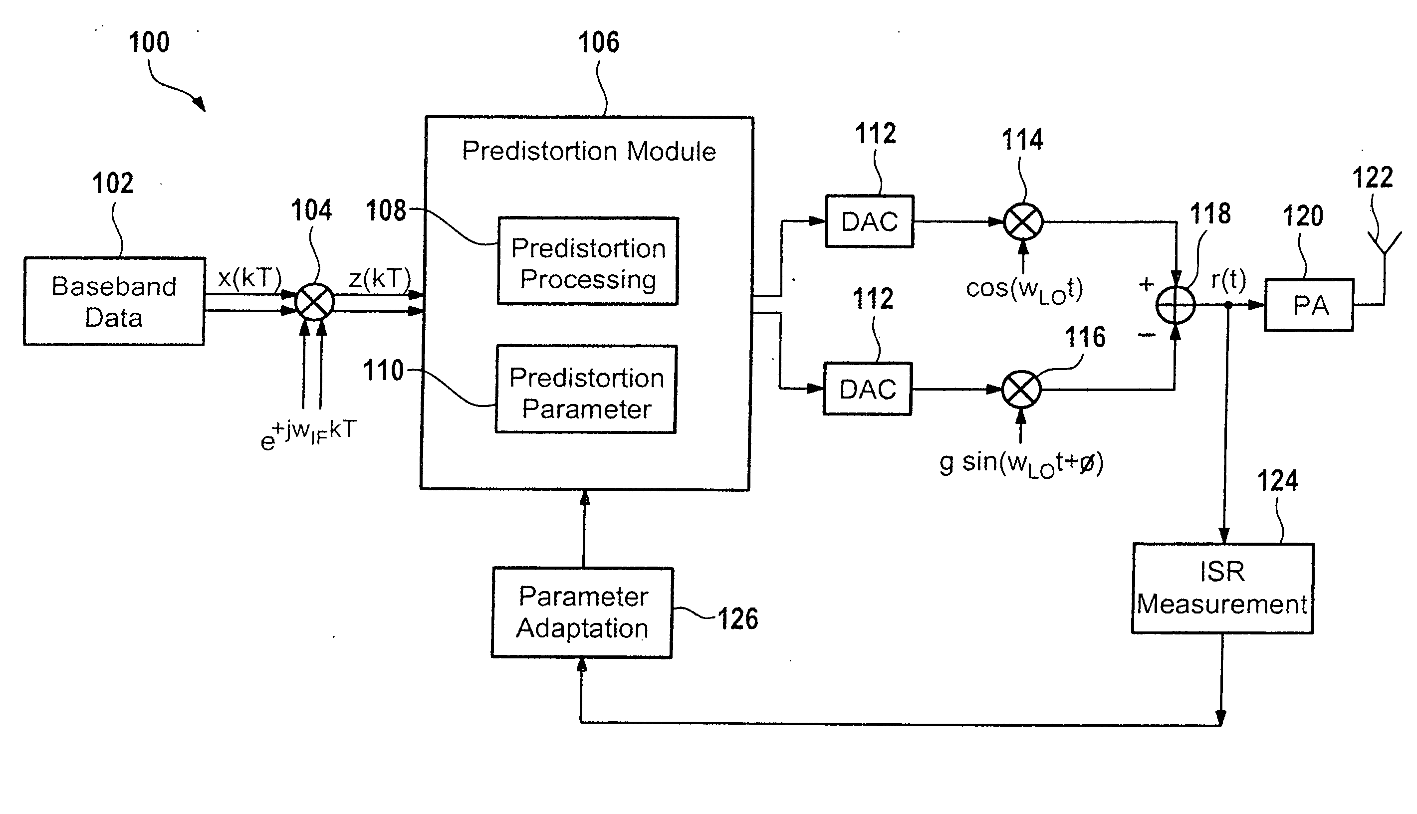
[0024]FIG. 1 shows a transmitter 100. The transmitter 100 has a digital-IF architecture. The upconversion of the transmit signal 102 from baseband to the RF carrier frequency is realized by a tuneable digital I / Q upconversion and a subsequent tuneable or fixed analog I / Q upconversion.

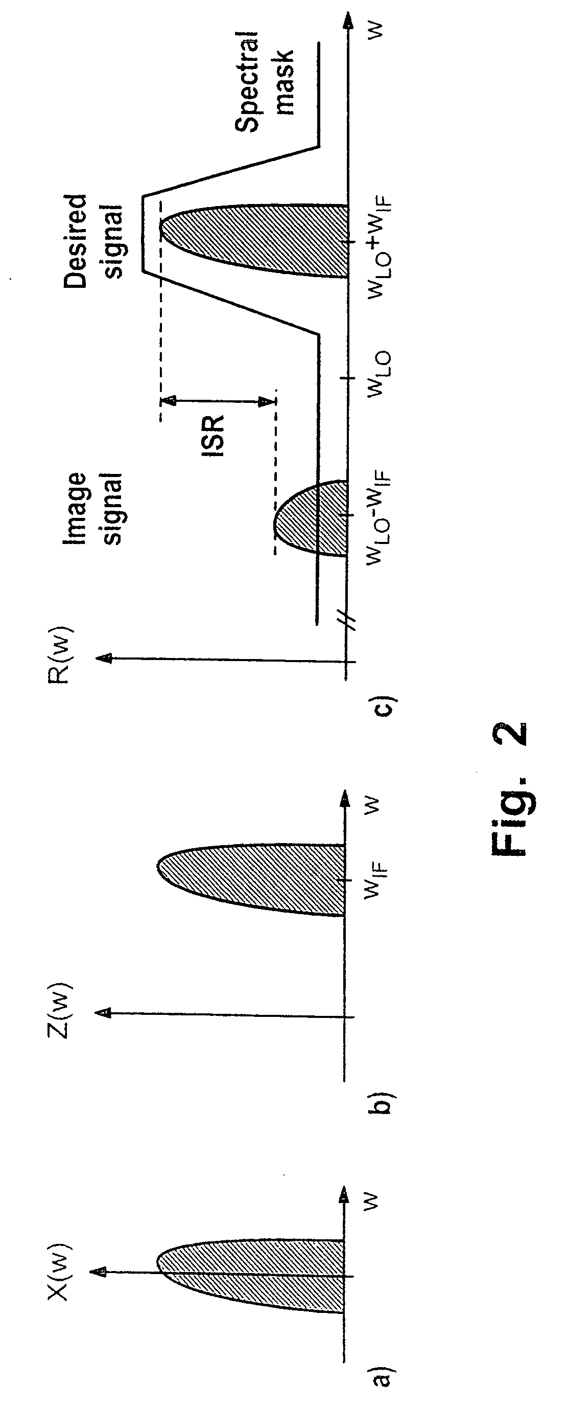
[0025] Perfectly balanced I / Q mixing (equal gain in the I- and in the Q-branch, exactly 900 phase shift between both phases of the oscillator) would lead to an infinite rejection of the image signal such that no costly image rejection filter would be required. However, due to hardware tolerances a perfectly balanced analog I / Q mixer is not feasible, resulting in a limited suppression of the image signal. A radiation of the unwanted residual image is critical, since the compliance with the spectral mask of the desired communication standard might be violated. Therefore the effects of I / Q imbalance are compensated by using digital signal processing.

[0026] The transmitter 100 has a digital mixer 104. The...


PUM


Abstract

The invention relates to a transmitter comprising: means for generating an intermediate frequency signal, means for predistortion of the intermediate frequency signal using a predistortion parameter, means for generating a radio frequency signal from the predistorted intermediate frequency signal, means for determining an image-to-signal-ratio of the radio frequency signal, means for adaptation of the predistortion parameter for reduction of the image-to-signal-ratio.

Description

TECHNICAL FIELD [0001] The present invention relates to the field of telecommunication, and more particularly to advanced transmitter architectures based on I / Q signal processing. The invention is based on a priority application EP 04 360 087.3 which is hereby incorporated by reference. BACKGROUND OF THE INVENTION [0002] The rejection of the image signal is a problem inherent to all receiver architectures. One of the benefits of a low-IF receiver is, that image rejection is realized by I / Q signal processing instead of a fixed analog filter, making it highly reconfigurable and cost-efficient. However, unavoidable imbalances between the I- and Q-branch leads to a limited image attenuation. [0003] M. Windisch and G. Fettweis, “Blind I / Q Imbalance Parameter Estimation and Compensation in Low-IF Receivers,” in Proceedings of the 1st International Symposium on Control, Communications and Signal Processing (ISCCSP 2004), (Hammamet, Tunisia), Mar. 21-24, 2004 shows an I / Q imbalance compensa...

Claims


Application Information

Patent Timeline
IPC IPC(8): H04L25/03
CPCH04B2001/0425H04B1/0475H03F1/3241
Inventor WINDISCH, MARCUS
Owner ALCATEL LUCENT SAS
Learn More