
Apparatus for decomposing an automatic cross connect system at a remote wiring hub

a technology of automatic cross-connect and remote wiring, which is applied in the direction of data switching networks, time-division multiplexing selection, duplex signal operation, etc., can solve the problems of high subscriber chum (i.e., turnover) rate of such broadband services, unfavorable activation of all subscriber lines, and high cost and time consumption of dispatches, so as to reduce the number of cross-points, reduce the cost, and reduce the effect of spa

Inactive Publication Date: 2006-03-30
RPX CORP +1
View PDF9 Cites 3 Cited by
  • Summary
  • Abstract
  • Description
  • Claims
  • Application Information

AI Technical Summary

Benefits of technology

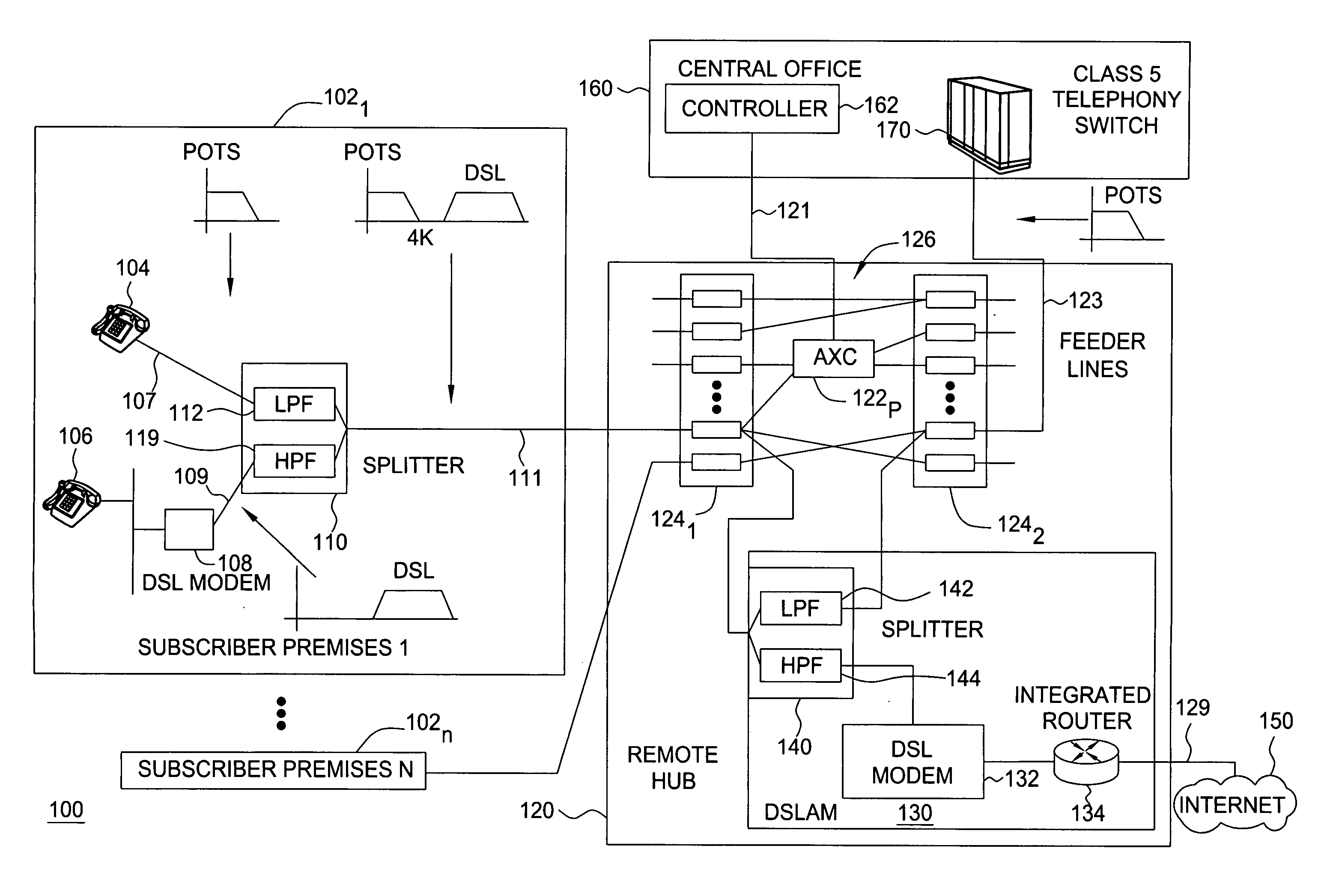
[0009] Accordingly, we have recognized that there is a need for an apparatus that assists in reducing dispatches at remote hubs. In one embodiment, an analog cross-connect (AXC) switch is deployed to further reduce the number of cross-connections at the hub. The AXC cross-connects subscriber lines to feeder lines under remote control, such that dispatches for these lines are not necessary.
[0012] Further reduction of an AXC switch for the canonical configuration may be provided by decomposing the AXC into two subsystems. The decomposed system has much fewer cross-points than the original system, and thereby has lower cost and requires less space. Lower costs and reduction in space are both critical features for a remote hub.
[0013] In another embodiment of the invention, one of the decomposed sub-systems is replaced by a splitter, further reducing the number of cross-points needed. The trade-off between the two embodiments is cost of the splitter versus the cost of an AXC switch.
[0014] Further reductions in the number of cross-points of the AXC switch may be provided by partitioning the AXC switch. Partitioning may be performed on either a non-decomposed or a decomposed AXC switch. The method of partitioning may illustratively be practiced for the decomposed embodiment to further reduce the number of cross-points further, but at the expense of more DSLAM ports or lower coverage rate.
[0015] The present invention is applicable for hubs providing POTS service, DSL service (with or without line-sharing), and an integrated POTS / DSL solution. Accordingly, the present invention helps alleviate space constraints at the hubs by reducing the cross-connect points and sizes of the switches.

Problems solved by technology

However, it is unlikely that all the subscriber lines are active.
This competitive market has resulted in a high subscriber chum (i.e., turnover) rate for such broadband services.
Dispatches are both costly and time consuming, and service provider would like to reduce these dispatches as much as possible.
Even with the MEMS technology, cost and space is still major a consideration in the deployment of AXCs at remote hubs.
Service providers still face the problem of whether to deploy a larger system, which provides more coverage but at higher costs, or a smaller systems that would be less costly but provide less coverage.

Method used


Image

  • Apparatus for decomposing an automatic cross connect system at a remote wiring hub
  • Apparatus for decomposing an automatic cross connect system at a remote wiring hub
  • Apparatus for decomposing an automatic cross connect system at a remote wiring hub

Examples


first embodiment

[0098]FIGS. 7A and 7B collectively depict a block diagram illustrating decomposition of the exemplary switch 122 of FIG. 5, in accordance with the present invention. As shown in FIG. 7A, the 785×785 switch is coupled between the group of 500 subscriber lines 302 and the group 502 of 500 feeder lines. Further, the switch 122 illustratively has a group 506 of 285 DSLAM lines coupled to the DSLAM 130, as well as a group 504 of 285 lines are fed back to the switch 122.

[0099] Referring to FIG. 7B, the decomposition of this exemplary switch 122 results in a decomposed switch 730 having two switch subsystems 7321 and 7322 (collectively switch subsystems 732), identical in structure, one on each side of the DSLAM 130. The first subsystem 7321 is situated between the subscriber lines 302 and the DSLAM 130 and comprises a first diagonal (or Y) switch 7341 and a first AXC module 7361. The second subsystem 7322 is situated between the feeder lines 502 and the DSLAM 130 and similarly comprises a...

second embodiment

[0111] The splitter 950 dedicates the LPF 952 and the HPF 954 to each subscriber line in the group 302. A low pass signal, which contains the POTS signal from a subscriber premise 102, is forwarded to the CO 160 via the feeder lines 123. A high pass signal, which contains the DSL signal, is forwarded to AXC 736 via one of the lines 734. The AXC switch 736 cross-connects the signal to an unused port at the DSLAM 130. Accordingly, this second embodiment effectively replaces one-half of the system by the splitter 950.

[0112] There are several trade-offs between the second decomposition (i.e., with the splitter) and the first decomposition (i.e., with the two subsystems). One consideration is the cost differences between the splitter 950 and an AXC module 732. Specifically, a splitter is much less expensive to purchase and implement than an AXC module. In particular, in many instances, the DSLAM 130 already implements the HPF, while the LPF is already implemented at the Class 5 voice swi...

third embodiment

[0127]FIGS. 12A and 12B collectively depict a flow diagram illustrating decomposing a non-canonical switch in accordance with the present invention. As shown in FIG. 12A, to support the DSL service, it is not necessary to have the number of feeder lines connected to the AXC equal the number of subscriber lines connected.

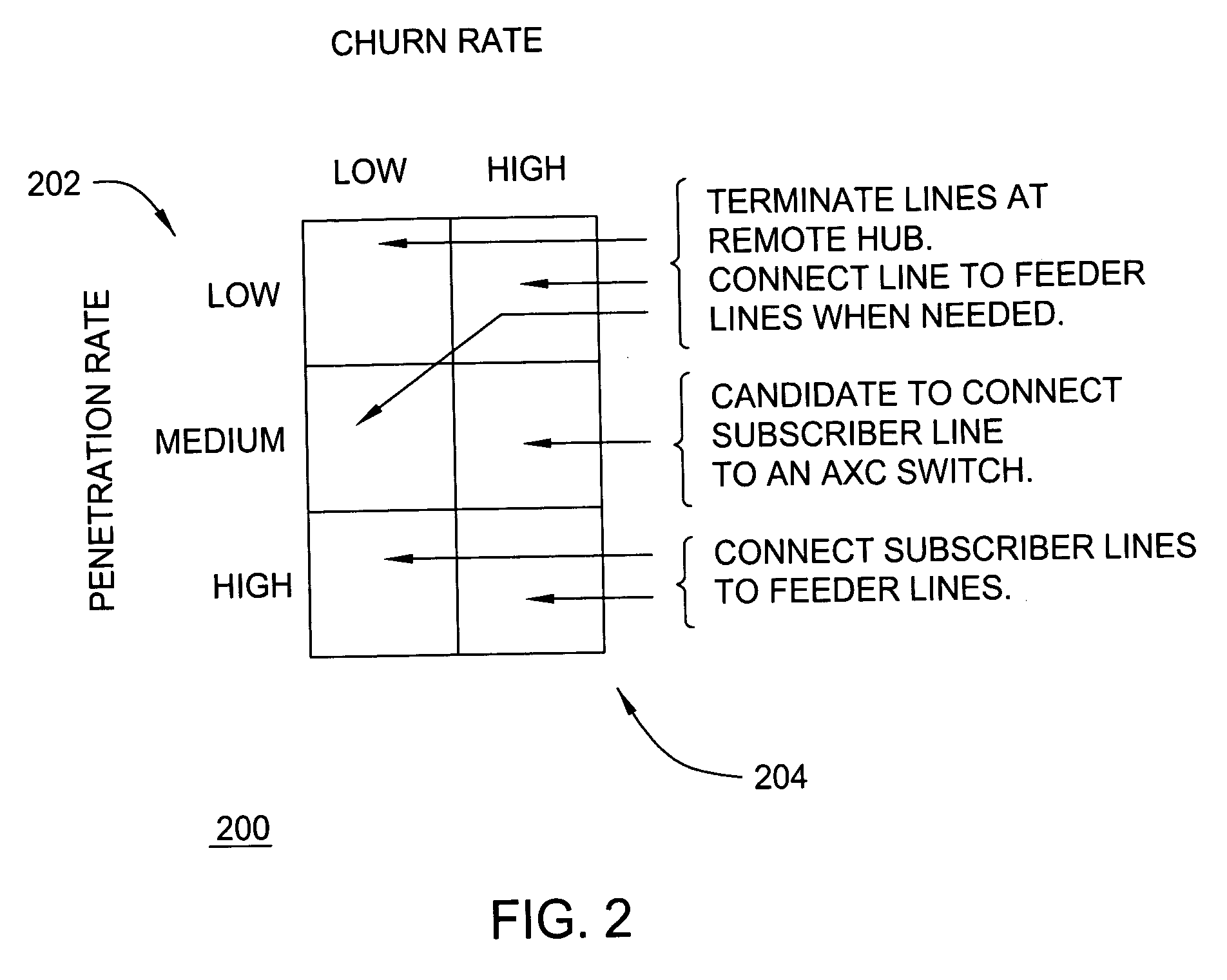
[0128] However, when deploying the non-canonical AXC, the service provider first needs to determine the characteristics of the subscriber line group being considered. The SP also needs to determine the penetration rate of POTS, DSL, and the line sharing option. Using the same example as discussed above, let the penetration rate for POTS and DSL is 60% and 50% respectively. Assume that of all the DSL subscribers, 80% of them will use the line sharing option. These assumptions results in the following: 40% of the line supports both the POTS and DSL service (i.e. line sharing option is used), 20% of the line supports only POTS service, 10% of the line supports DSL servi...


PUM


Abstract

Apparatus for providing connectivity at a hub having a plurality of subscriber lines and a plurality of feeder lines. The apparatus includes a first switch module for coupling to N of the plurality of subscriber lines, where N is an integer. The first switch module is also for coupling to a digital subscriber line access modem (DSLAM) at the hub. A second switch module is coupled to the first switch module and the DSLAM. The second switch module is also adapted for coupling to M of the plurality of feeder lines at the hub, where M is an integer.

Description

FIELD OF INVENTION [0001] The present invention relates to providing connectivity for telephony services at a remote hub. More specifically, the invention relates to design and implementation of an analog cross-connect switch deployed between subscriber lines and feeder lines at a remote hub. BACKGROUND OF INVENTION [0002] Telephony service providers of telephony (e.g., POTS and DSL) services utilize outside plants that provide connectivity from the subscribers of the service to the central offices (CO) of the service provider. The most common media used in the outside plant is copper loops. A copper loop typically transverses from the CO to the subscriber homes via manholes, wiring cabinets, pedestals, and poles before terminating at the network interface device (NID) at the subscribers' premises. [0003] The manholes and cabinets represent major concentration sites for the wiring. Each cabinet or manhole (i.e., remote hub) typically serves about 500 homes. Each home is wired with a...

Claims


Application Information

Patent Timeline
IPC IPC(8): H04M1/00H04M9/00
CPCH04M11/062H04Q3/605H04Q11/04H04Q2213/13298H04Q2213/13039H04Q2213/1304H04Q2213/13076H04Q2213/1302
Inventor CHU, THOMAS P.GAGEN, PAUL FRANCISMAGEE, FRANCIS ROBERT
Owner RPX CORP
Learn More