Outer case for non-aqueous electrolyte battery and method of producing the same

a non-aqueous electrolyte battery and outer case technology, applied in the direction of cell components, cell component details, electrochemical generators, etc., can solve the problems of many problems to be solved, tubing may be partially wrinkled, and the conventional external packaging method has not yet satisfied all the demands, so as to improve the capacity-weight efficiency of the battery pack, ensure mechanical strength, and improve the effect of capacity-volume efficiency

Inactive Publication Date: 2006-03-30
SONY CORP +1
View PDF2 Cites 36 Cited by
  • Summary
  • Abstract
  • Description
  • Claims
  • Application Information

AI Technical Summary

Benefits of technology

[0011] An advantage of the present invention is as follows. An outer casing of a non-aqueous electrolyte battery is formed by joining together a casing body and a cover that are different in configuration from each other, or by joining together a pair of mating molded pieces of the same configuration. Joint portions for joining together the two constituent members of the outer casing are formed integrally on the two constituent members, respectively, in the form of a stepped structure. Therefore, the outer casing can be formed thin in thickness, and yet the required mechanical strength can be ensured satisfactorily.
[0012] Another advantage of the present invention is that the capacity-volume efficiency and the capacity-weight efficiency of the battery pack can be improved.
[0013] Still another advantage of the present invention is that the production method for the outer casing can employ injection molding process that is simple and capable of mass production.
[0014] A further advantage of the present invention is that because a part of the outer casing can be formed by injection molding, the freedom of configuration increases, so that the outer casing can be formed into a product that is tasteful and excellent in design.
[0015] The present invention adopts the following means to solve the above-described problems.
[0016] An outer casing for externally packaging a non-aqueous electrolyte battery according to a first feature of the present invention is an outer casing (4) characterized by including a rectangular casing body (4a) formed of a synthetic resin for accommodating the non-aqueous electrolyte battery. The casing body has a casing body outer peripheral frame (9) integrally provided on the outer peripheral edge of a side of the casing body. The outer casing (4) further includes a cover (4b) including a film-shaped side panel (4c) formed of a synthetic resin that covers an open side of the non-aqueous electrolyte battery accommodated in the casing body (4a). The cover (4b) further includes a cover outer peripheral frame (10) formed of a synthetic resin that is integrally fixed to the outer peripheral edge of the side panel (4c). Further, the outer casing (4) includes joint portions for integrally joining together the casing body outer peripheral frame (9) and the cover outer peripheral frame (10) in opposed relation to each other.

Problems solved by technology

However, the conventional externally packaging methods have not yet satisfied all the demands but still have many problems to be solved.
If this battery is covered with thin hear-shrinkable tubing, the tubing may be partially wrinkled.
Therefore, there is a problem in terms of reliability in mass production of batteries of stable quality.
Meanwhile, injection molding is excellent in mass productivity but disadvantageous for the following reason.
Thus, it is even more difficult to obtain a thin molded part.
Therefore, a thick outer casing that would lessen the advantageous feature of lithium-ion polymer secondary batteries cannot be adopted.
However, the thin-walled molded part does not completely cover the outer surface of the housed component.
Therefore, it cannot be employed for the above-described outer packaging of batteries.

Method used


Image

  • Outer case for non-aqueous electrolyte battery and method of producing the same
  • Outer case for non-aqueous electrolyte battery and method of producing the same
  • Outer case for non-aqueous electrolyte battery and method of producing the same

Examples


first embodiment

[First Embodiment]

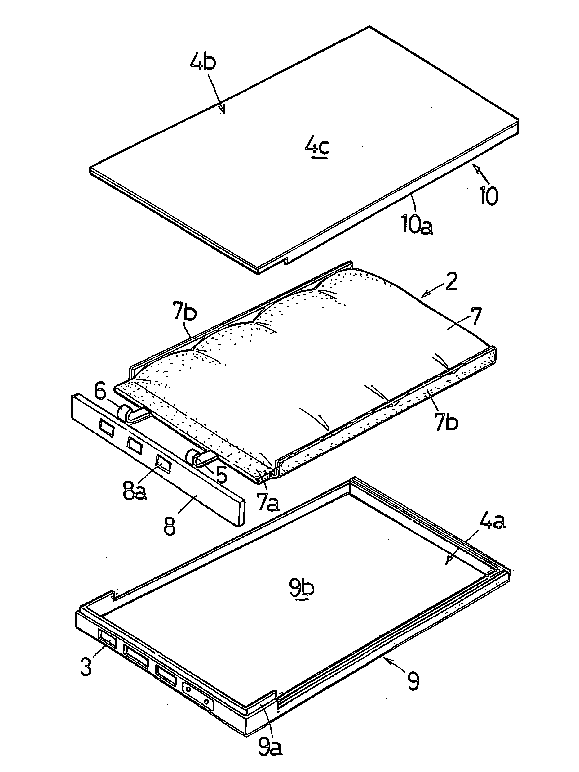
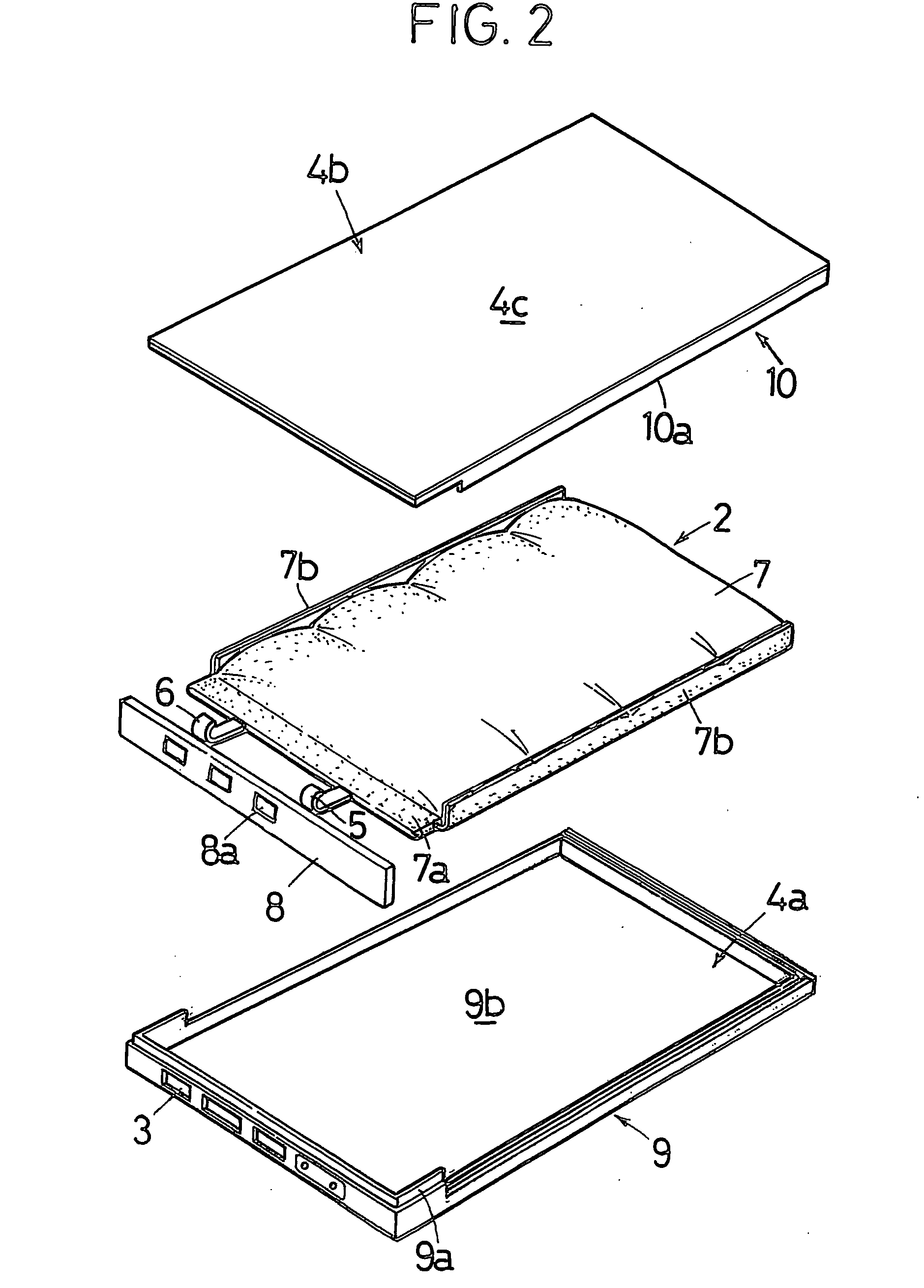
[0058] A first embodiment of the present invention will be described below. FIG. 1 is an external view of a lithium-ion polymer secondary battery 1 to which the present invention is applied. FIG. 2 is an exploded view of the lithium-ion polymer secondary battery 1. FIG. 3 is a sectional view taken along the line X-X in FIG. 1. FIG. 4 is a sectional view taken along the line Y-Y in FIG. 1.

[0059] The lithium-ion polymer secondary battery 1 is a repeatedly rechargeable battery, which is used as a battery for a cellular phone or the like. The lithium-ion polymer secondary battery 1 is a thin and lightweight battery implemented by replacing an electrolytic solution with a gel-state polymer electrolyte. In this example, the lithium-ion polymer secondary battery 1 is a thin battery (e.g. 3.8 mm in thickness) implemented so as to be usable in a cellular phone or the like.

[0060] An outer casing 4 of the lithium-ion polymer secondary battery 1 is a synthetic resin casing-p...

third embodiment (

[Third Embodiment (Thermoforming of Sheet Material)]

[0090] In either of the foregoing first and second embodiments, the sheet material 4c of the cover 4b for forming a side of the outer casing 4 is formed into a predetermined shape in the injection-molding mold. In this embodiment, the sheet material is thermoformed before it is inserted into the injection-molding mold. FIG. 14 is a sectional view of a thermoforming die 25a for vacuum forming. As shown in FIG. 14, a sheet material 20b, which is a thermoplastic sheet, is fixed on the thermoforming die 25a and heated to soften with a heater 34. The softened sheet material 20b is sucked onto the thermoforming die 25a through a vacuum circuit 35 communicating with a vacuum device, thereby forming the sheet material 20b.

[0091] Thereafter, the outer periphery of the thermoformed sheet material 20b is trimmed with a cutting device (not shown). As shown in FIG. 15, the thermoformed and trimmed sheet material 20b is inserted into an injecti...

fourth embodiment

[Fourth Embodiment] (Thermoforming of Sheet Material)

[0093] A fourth embodiment is the same as the third embodiment in that the sheet material is thermoformed before it is inserted into an injection-molding mold. The fourth embodiment is also the same as the third embodiment in that the outer periphery of the thermoformed sheet material 20c is trimmed with a cutting device (not shown). As shown in FIG. 18, however, the thermoformed and trimmed sheet material 20c has burr 31 occurring on the cut surface as a result of the cutting process.

[0094] It is necessary to carry out a deburring step of removing the burr 31 before or after ultrasonic welding performed with an ultrasonic welding apparatus after the above-described injection molding. This embodiment enables the deburring step to be omitted. An outer peripheral portion 32 of the sheet material 20c constituting the cover outer peripheral frame 10 is cut shorter than the thickness h (see FIG. 19) of the cover outer peripheral frame...


PUM

PropertyMeasurementUnit
thicknessaaaaaaaaaa
thicknessaaaaaaaaaa
thicknessaaaaaaaaaa

Abstract

An outer casing of a non-aqueous electrolyte battery is capable of being mass-produced as well as thin and resistant to damage. The outer casing 4 comprises a casing body 4a and a cover 4b. After being internally packaged, a non-aqueous electrolyte battery 2, e.g. a lithium-ion polymer secondary battery, is sandwiched between the casing body 4a and the cover 4b, which are then joined together integrally. The cover 4b is formed from a film-shaped sheet material 4c of a synthetic resin to make the outer casing 4 thin. The casing body 4a and the cover 4b have a casing body outer peripheral frame 9 and a cover outer peripheral frame 10, respectively, formed by injection molding. Joint portions of the casing body 4a and the cover 4b have stepped portions 9a and 10a, respectively. The stepped portions ensure the mechanical strength against shock and impact. With this structure, the outer casing 4 is resistant to damage.

Description

TECHNICAL FIELD [0001] The present invention relates to an outer casing for externally packaging a non-aqueous electrolyte battery body packaged in an aluminum laminated film or the like and also relates to a production method for the outer casing. More particularly, the present invention relates to an outer casing of a non-aqueous electrolyte battery that externally packages a non-aqueous electrolyte battery element with a thin casing body formed of a synthetic resin or a film-shaped sheet material having a frame member of a synthetic resin integrally fixed to the outer periphery thereof. The present invention also relates to a production method for the outer casing. BACKGROUND ART [0002] Conventionally, a lithium-ion battery is housed in a metal case, e.g. a steel can, or an aluminum can, and a polymer battery is packaged in an aluminum laminated film. These batteries need to be further externally packaged to protect them against shock from dropping or other external impact. There...

Claims


Application Information

Patent Timeline
Patent Type & Authority Applications(United States)
IPC IPC(8): H01M2/08H01M2/04H01M2/10H01M10/052H01M10/36
CPCH01M2/1061H01M10/052Y10T29/4911Y10T29/49108Y10T29/49114Y02E60/10H01M50/209H01M50/20H01M50/00
Inventor HIRATSUKA, MASARUSAKAMOTO, MITSUONARITOMI, MASANORI
Owner SONY CORP
Why Eureka
Try Eureka