Thin film coating and temporary protection technology, insulating glazing units, and associated methods

Inactive Publication Date: 2006-04-06
CARDINAL CG
View PDF99 Cites 17 Cited by
  • Summary
  • Abstract
  • Description
  • Claims
  • Application Information

AI Technical Summary

Benefits of technology

[0010] In certain embodiments, the invention provides a method of processing substrates. The method comprises providing a first sheet of glass, the first glass sheet having opposed first and second major surfaces. In the present embodiments, the first glass sheet is conveyed through a single sputter coater (or through multiple coaters sharing one continuous path of substrate travel), and coatings are deposited onto both the first and second major surfaces in a single pass of the first glass sheet through the sputter coater (and/or along the single path of substrate travel). Here, the sputter depositing involves applying a photocatalytic coating to the first major surface of the first glass sheet by sputtering upwardly from a first sequence of targets. This sequence of targets includes one or more targets comprising a sputterable target material selected from the group consisting of a pure or substantially pure titanium material, a titanium alloy material, a titanium oxide material, and a compound including titanium and silicon. The sputter depositing also involves applying a low-emissivity coating to the second major surface of the first glass sheet by sputtering downwardly from a second sequence of targets. This sequence of targets includes one or more targets comprising a sputterable target material sel

Problems solved by technology

Unfortunately, infrared (IR) energy from the sun entering a room through a window can quickly raise the temperature in the room to an uncomfortable level.
Thick titanium dioxide, unfortunately, produces relatively high levels of visible reflectance.
It has been discovered that this high visible reflection actually exaggerates the appearance of dirt on a window, resulting in a window that looks particularly dirty.
This, of course, is not desirable, as the very purpose of a photocatalytic coating is to provide a cleaner window.
Moreover, when a substrate is provided with both a photocatalytic coating and a low-emissivity coating, the reflected color tends to be less than ideal.
Thus, when such IG units are installed in the wall of a building, the photocatalytic coating will tend to be exposed to a variety of contamination sources (painters finishing nearby areas of the building, etc.).
While photocatalytic coatings may have some ability to remove such contaminants by virtue of photoactivity, excessive contamination and / or inorganic contamination may not be removed completely or quickly enough by the self-cleaning action of the coating.
In most cases, it will be unacceptable for the activity of the photocatalytic coating to degrade such adhesive to the point where the masking actually falls, or sags, off the coated surface.
Moreover, the activity of the coating should not alter the character of the masking adhesive in such a way that the adhesive and / or the masking film is rendered unacceptably difficult to remove from the coated surface.

Method used


Image

  • Thin film coating and temporary protection technology, insulating glazing units, and associated methods
  • Thin film coating and temporary protection technology, insulating glazing units, and associated methods
  • Thin film coating and temporary protection technology, insulating glazing units, and associated methods

Examples


Embodiment Construction

[0025] The following detailed description should be read with reference to the drawings, in which like elements in different drawings are numbered identically. The drawings, which are not necessarily to scale, depict selected embodiments and are not intended to limit the scope of the invention. Examples of constructions, materials, dimensions, and manufacturing processes are provided for selected elements. All other elements employ that which is known to those of skill in the field of the invention. Those skilled in the art will recognize that many of the examples provided have suitable alternatives that can be utilized.

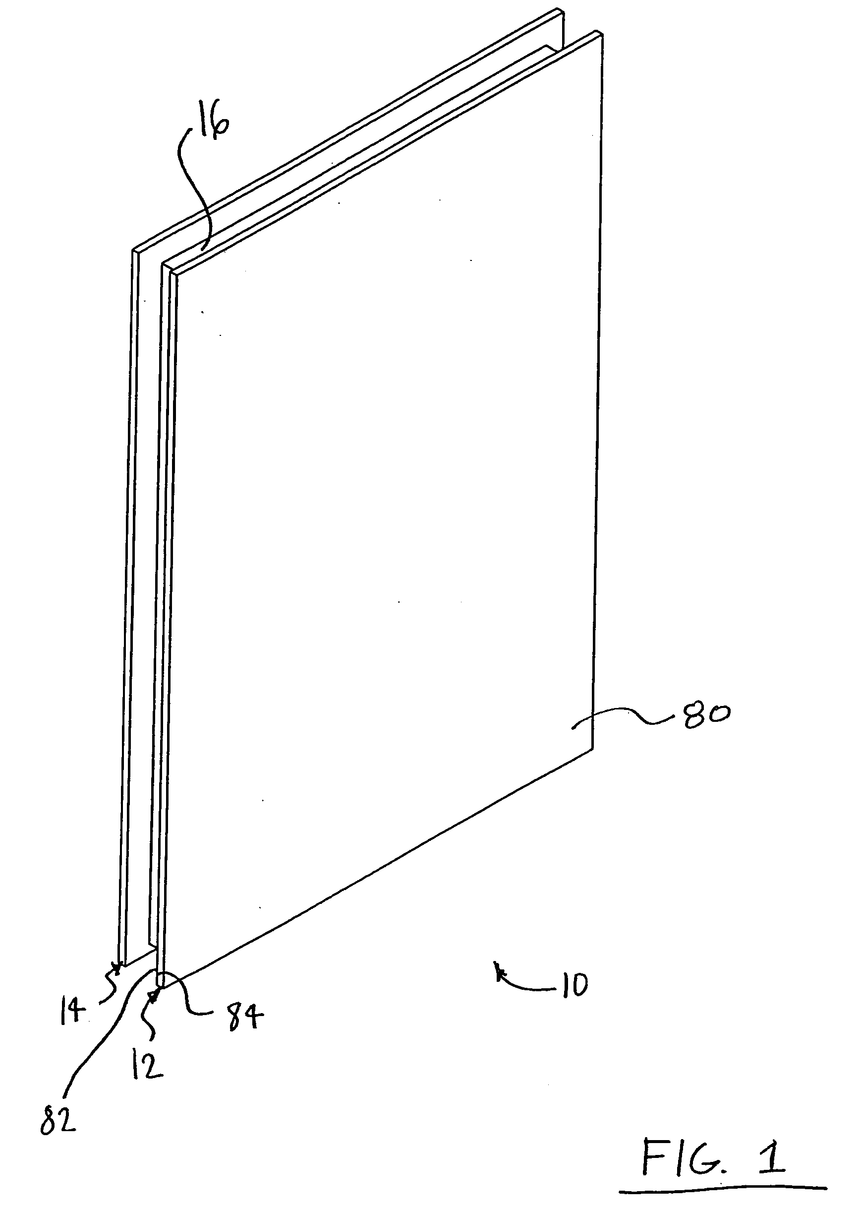
[0026]FIG. 1 is a perspective view of an insulating glazing unit 10 in accordance with an exemplary embodiment of the present invention. Insulating glazing unit 10 comprises a first pane 12 having a first face 80, a second face 82, and a periphery 84 extending between first face 80 and second face 82. In the embodiment of FIG. 1, insulating glazing unit 10 also comp...


PUM

PropertyMeasurementUnit
Thicknessaaaaaaaaaa
Photocatalytic propertiesaaaaaaaaaa
Adhesion strengthaaaaaaaaaa

Abstract

The present invention in some embodiments provides sputter deposition techniques for applying thin film and thereafter applying over the sputtered film a temporary protective film. The thin film can optionally be applied by sputtering a target in a gaseous sputtering atmosphere containing an oxidizing gas and / or an inert gas. The invention in some embodiments relates to an insulating glazing unit or a monolithic pane having a thin film coating, deposited for example by sputtering, on at least one major surface, the thin film coating carrying a temporary protective film. The invention also provides embodiments involving high efficiency methods for producing such products.

Description

FIELD OF THE INVENTION [0001] The present invention relates in some embodiments to sputter deposition techniques for applying thin film and thereafter applying over the sputtered film a temporary protective film. The thin film can be applied by sputtering a target in a gaseous sputtering atmosphere containing an oxidizing gas and / or an inert gas. The invention in some embodiments relates to an insulating glazing unit or a monolithic pane having a thin film coating, deposited for example by sputtering, on at least one major surface, the thin film coating carrying a temporary protective film. The invention also provides embodiments involving high efficiency methods for producing such products. BACKGROUND OF THE INVENTION [0002] In the coated glass industry, it is common to apply one or more thin films onto glass to impart desired properties in the coated glass. For example, in manufacturing glass for window and door applications, it is advantageous to apply infrared-reflective coating...

Claims


Application Information

Patent Timeline
IPC IPC(8): C23C14/00C23C14/32
CPCC03C17/36C03C17/3644C03C17/3681C03C17/38C03C17/42C03C2217/212C03C2217/71C03C2217/75C03C2218/154C03C2218/156C03C2218/328C03C2218/355C03C2218/36C03C2218/365C23C14/083E06B3/6715
Inventor KRISKO, ANNETTE J.GROMMESH, ROBERT C.
Owner CARDINAL CG
Why Eureka
Try Eureka