Radiographic imaging apparatus and system, method therefor, and program

Active Publication Date: 2006-04-06
CANON KK
View PDF6 Cites 17 Cited by
  • Summary
  • Abstract
  • Description
  • Claims
  • Application Information

AI Technical Summary

Benefits of technology

[0010] Also available is a method of image capturing by irradiating an object with continuous radiation without synchronizing the radiographic imaging apparatus with the imaging means. In this method, however, an image of a moving object blurs and this results in a deterioration of the image quality.
[0011] The present invention has been made in consideration of the above problems, and has as its object to provide a radiographic imaging apparatus and system which can more reliably make a radiation generator and an imaging means operate synchronously.
[0012] In order to achieve the above object, according to a first aspect of the present invention, there is provided a radiographic imaging apparatus comprising an imaging means which captures a radiation image based on a radiation pulse emitted from a radiation generator, a radiation pulse detection means which detects the radiation pulse, and a control means which controls the imaging means based on a detection result obtained by the radiation pulse detection means, wherein the control means includes a computing unit which computes a pulse width and period of the radiation pulse based on the detection result obtained by the radiation pulse detection means, and controls the imaging means based on the pulse width and period of the radiation pulse which are computed by the computing unit.

Problems solved by technology

However, since a device such as a relay is used for the radiation I/F 403, a timing delay occurs.
In addition, the relay device used for the radiation I/F has a large delay and is unstable, and hence it is difficult to perform accurate timing control.
That is, a timing limitation ten

Method used


Image

  • Radiographic imaging apparatus and system, method therefor, and program
  • Radiographic imaging apparatus and system, method therefor, and program
  • Radiographic imaging apparatus and system, method therefor, and program

Examples


Embodiment Construction

[0028] A preferred embodiment of the present invention will be described below with reference to the accompanying drawings. This embodiment will exemplify X-rays as radiation. However, the present invention is not limited to this, and radiation includes a rays, B rays, and y rays.

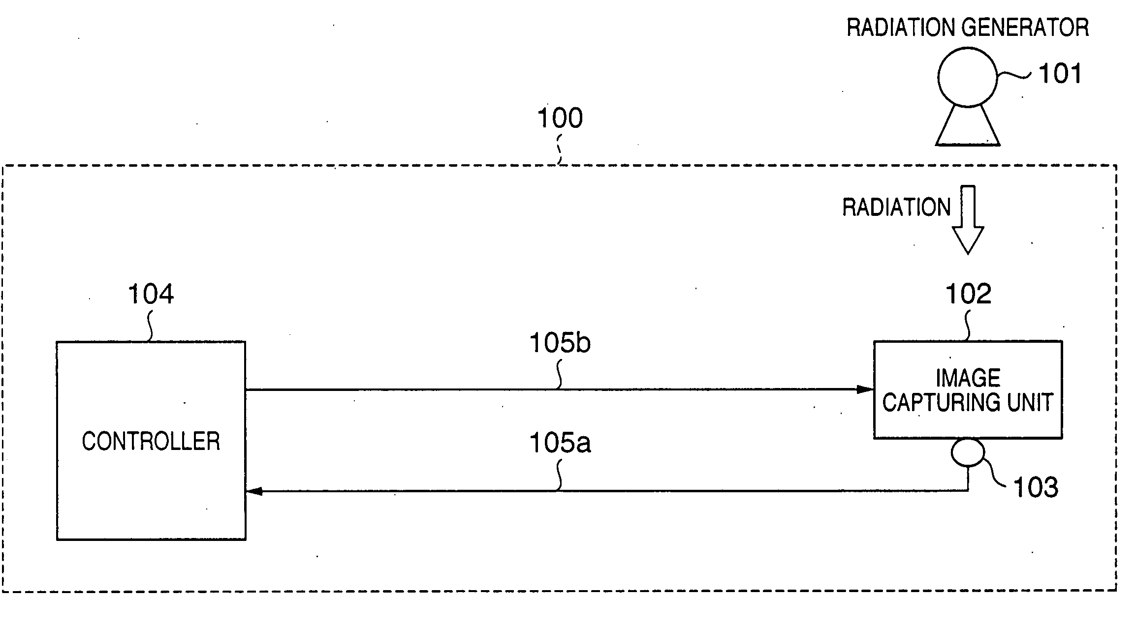
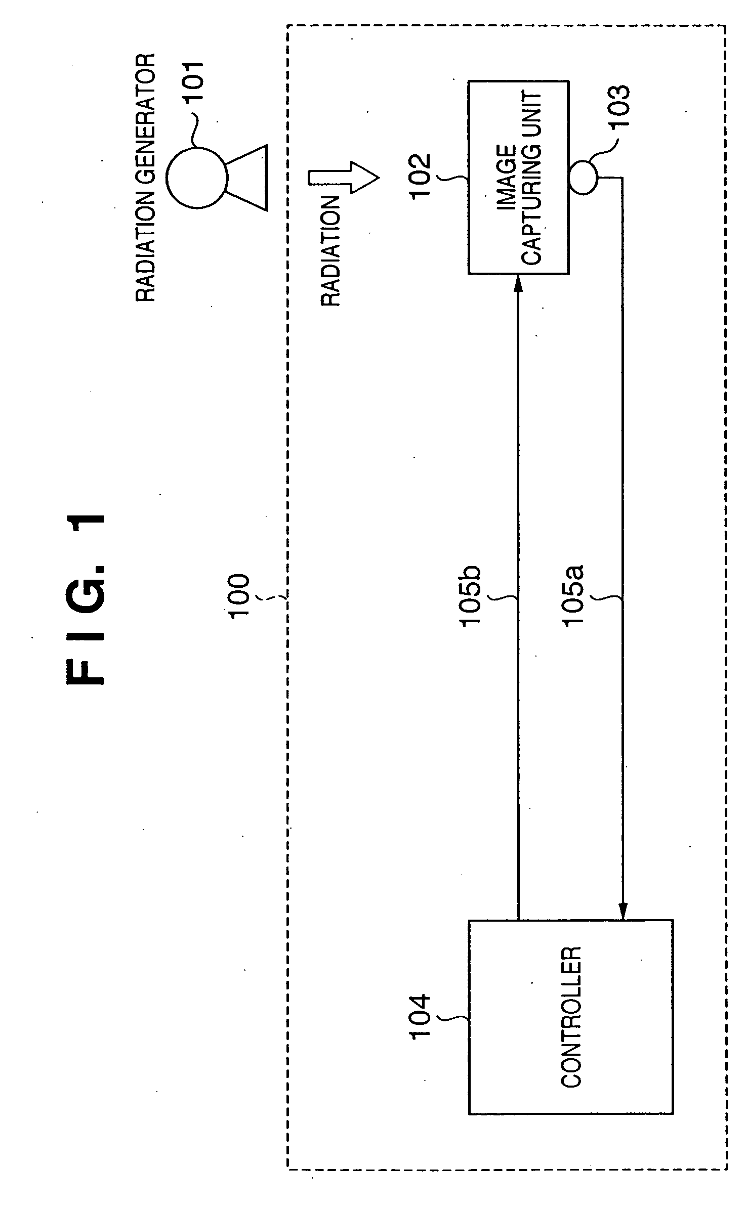
[0029]FIG. 1 is a view showing the schematic arrangement of a radiographic imaging apparatus according to a preferred embodiment of the present invention.

[0030] Referring to FIG. 1, reference numeral 100 denotes a radiographic imaging apparatus, which includes an imaging means 102, a radiation pulse detection means 103, and a control means 104. A radiation generator 101 irradiates the imaging means 102 of the radiographic imaging apparatus 100 with pulse-like radiation (to be referred to as a radiation pulse hereinafter). In this manner, a radiographic imaging system including the radiographic imaging apparatus 100 and radiation generator 101 is formed. The imaging means 102 captures a radiation image by ...


PUM


Abstract

A radiographic imaging apparatus includes an imaging means which captures a radiation image based on a radiation pulse emitted from a radiation generator, a radiation pulse detection means which detects the radiation pulse, and a control means which controls the imaging means based on a detection result obtained by the radiation pulse detection means. The control means includes a computing unit which computes the pulse width and period of the radiation pulse based on the detection result obtained by the radiation pulse detection means, and controls the imaging means based on the pulse width and period of the radiation pulse which are computed by the computing unit.

Description

FIELD OF THE INVENTION [0001] The present invention relates to a radiographic imaging apparatus and system which performs radiography using radiation or the like, a method therefor, and a program. BACKGROUND OF THE INVENTION [0002]FIG. 4 is a block diagram showing the schematic arrangement of a radiographic imaging system including a conventional radiographic imaging apparatus. FIG. 5 is a schematic circuit diagram of an imaging means used in conventional radiographic imaging apparatus. FIG. 6 is a timing chart showing the driving timing for a conventional radiographic imaging apparatus. [0003] As shown in FIG. 4, a conventional radiographic imaging system 400 includes a radiation generator 401, an imaging means 402, a radiation I / F 403, and a control means 404 (see, for example, Japanese Patent Laid-Open No. 08-130682 and U.S. Pat. Nos. 5,677,940 and 6,515,286). The imaging means 402 is connected to the control means 404 via cable 405c. Control signals such as driving pulses are su...

Claims


Application Information

Patent Timeline
IPC IPC(8): G01T1/24
CPCA61B6/00A61B6/4233A61B6/4405A61B6/563H04N5/32
Inventor KAMESHIMA, TOSHIO
Owner CANON KK
Why Eureka
Try Eureka