Table saw cart

Inactive Publication Date: 2006-04-06
SUPER MADE PRODS
View PDF9 Cites 26 Cited by
  • Summary
  • Abstract
  • Description
  • Claims
  • Application Information

AI Technical Summary

Benefits of technology

[0007] Another purpose yet of the present invention is to provide a table saw cart that allows wider working range. To achieve the purpose, the rear legs of a foldable frame of the cart are made in a form of handle to push around the cart as desired with the least efforts.
[0008] Another purpo

Problems solved by technology

However, no safety positioning means is provided to the prior art resulting in displacement of the cart due to the strong v

Method used


Image

  • Table saw cart
  • Table saw cart
  • Table saw cart

Examples


Embodiment Construction

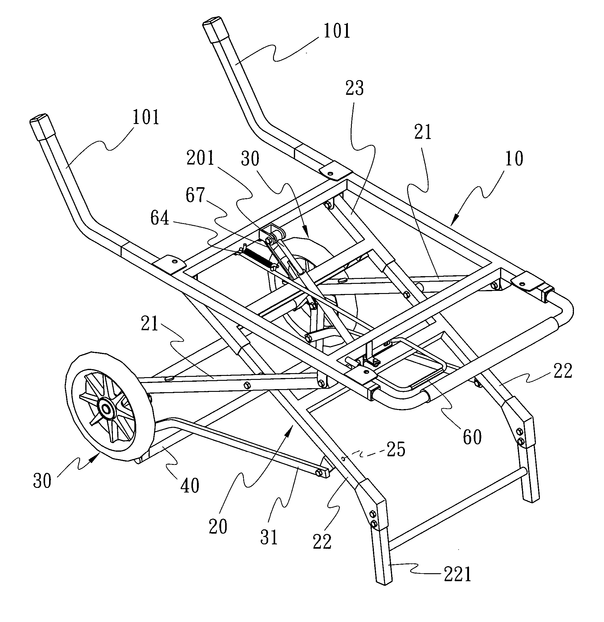
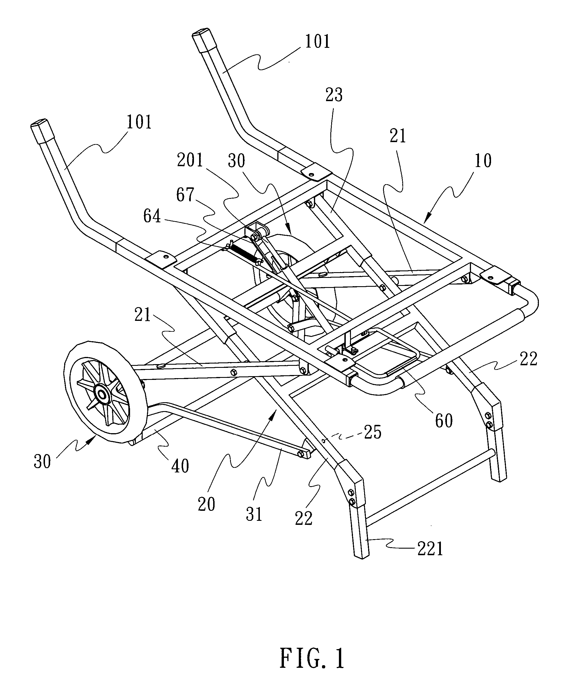
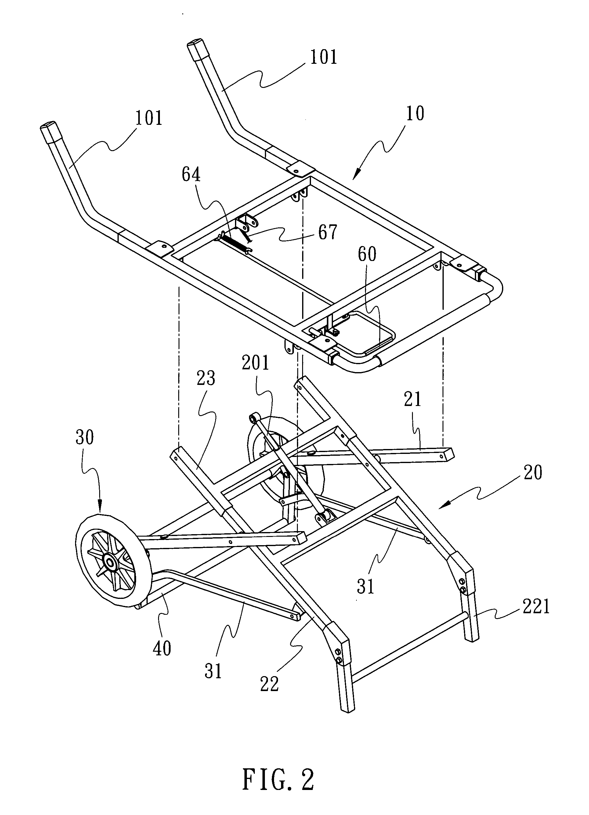
[0020] Referring to FIGS. 1 through 4, a preferred embodiment of the present invention, a table saw cart is essentially comprised of a carrier 10, a foldable frame 20 and a pair of wheels 30. Wherein, the carrier 10 related to a U-shaped frame provided on the upper end of the foldable frame 20 secures a machine 50 (e.g., a sawing machine or similar machine) and has an rod 101 extending upwardly from both open ends of the carrier 10.

[0021] The foldable frame 20 related to a cross frame with its upper end fixed to the carrier 10 contains a pair of front legs 21 and a pair of rear legs 22; both rear legs 22 are each movably coupled to a retractable tube 23 with the terminal 221 of each rear leg 22 curved downward so that when the cart is left in standing position, both terminals 221 define a handle to push the cart as illustrated in FIG. 5. Furthermore, a pressure rod 201 is connected at a selected location between the foldable frame 20 to server as a buffer in elevation and folding i...


PUM


Abstract

A table saw cart including a carrier, a foldable frame, and a pair of wheels; a stretcher between wheels; a connection rod between the stretcher and rear legs of the foldable frame. The wheels are raised above the floor by the stretcher to prevent displacement of cart while the machine thereon is operating. Two extension rods extend from the open end of carrier to secure the cart with the wheels. Both rear legs define a handle; and a pull rod and three locking pins control the elevation of the cart to secure the cart in either of a folded positioned or a raised, standing position.

Description

BACKGROUND OF THE INVENTION [0001] (a) Field of the Invention [0002] The present invention is related to a tool cart, and more particularly, to one that carries a sawing machine or similar machine. [0003] (b) Description of the Prior Art: [0004] A table saw cart of the prior art for carrying a sawing machine or similar machine as taught in U.S. Pat. Nos. 6,722,618 and 6,314,893 provides a cart exclusively designed for carrying the sawing machine or similar machine to operate thereon and is adapted with foldable frame legs. However, no safety positioning means is provided to the prior art resulting in displacement of the cart due to the strong vibration from the machine while operating. Therefore, the prior art is vulnerable to operating problems and safety concerns. SUMMARY OF THE INVENTION [0005] The primary purpose of the present invention is to provide a table saw cart that prevents displacement of the cart while the machine it carries is operating. To achieve the purpose, a stre...

Claims


Application Information

Patent Timeline
IPC IPC(8): B62B7/00
CPCB25H1/04B62B1/26B62B5/049B62B2205/22
Inventor WU, SAN-CHING
Owner SUPER MADE PRODS
Why Eureka
Try Eureka