Push-pull bridge type magnetic sensor for high-intensity magnetic field

A magnetic field sensor and magnetic sensor technology, applied in the field of magnetic sensors, can solve the problems of not wide enough linear range and inapplicability, and achieve the effects of good linearity, low power consumption and small offset

Active Publication Date: 2014-02-19
MULTIDIMENSION TECH CO LTD
View PDF6 Cites 13 Cited by
  • Summary
  • Abstract
  • Description
  • Claims
  • Application Information

AI Technical Summary

Problems solved by technology

However, the existing TMR magnetic sensors are still not suitable for working in high-intensity magnetic fields, and the linear range is not wide enough

Method used


Image

  • Push-pull bridge type magnetic sensor for high-intensity magnetic field
  • Push-pull bridge type magnetic sensor for high-intensity magnetic field
  • Push-pull bridge type magnetic sensor for high-intensity magnetic field

Examples


Embodiment

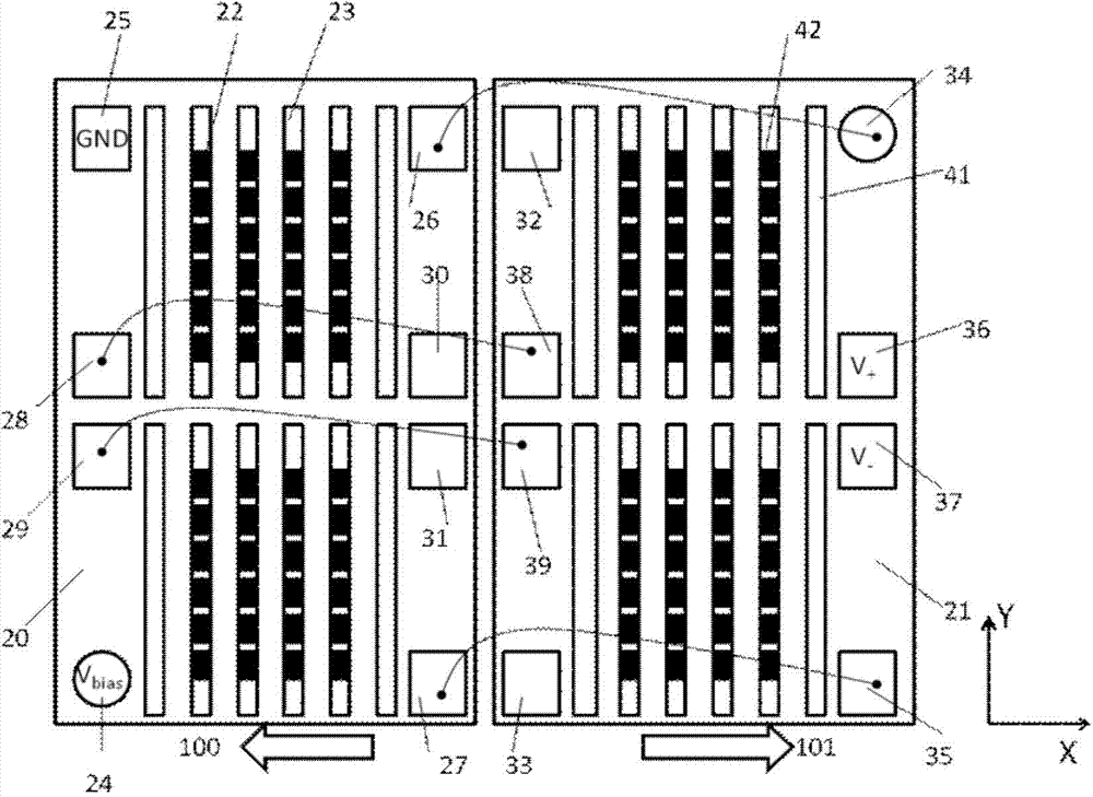
[0038] figure 2 It is a structural schematic diagram of the push-pull bridge type magnetic sensor in the present invention. The sensor includes a push arm substrate 20, a pull arm substrate 21, a plurality of magnetoresistive sensing elements 22, 42, a plurality of push arm attenuators 23, a pull arm attenuator 41, and welding pads 24-39. Wherein, the magnetoresistive sensing element 22, the push arm attenuator 23, and the pads 24-31 are deposited on the push arm substrate 20, and the magnetoresistive sensing element 42, the pull arm attenuator 41, and the pads 32-39 are deposited on the push arm substrate 20. On the arm substrate 21, the push arm substrate 20 and the pull arm substrate 21 are the same except for the different directions. The long axis direction of the push arm attenuator 23 and the pull arm attenuator 41 is the Y axis direction, and the short axis direction is the X axis direction. Pads 24, 25, 36, and 37 are respectively used as power supply terminals V ...


PUM


Abstract

The invention discloses a push-pull bridge type magnetic sensor for a high-intensity magnetic field. The sensor comprises two substrates, magnetoresistance sensing elements, a push arm attenuator and a pull arm attenuator. The magnetization directions of pinning layers of the magnetoresistance sensing elements on the same substrate are same, the magnetization directions of pinning layers of the magnetoresistance sensing elements on different substrates are opposite, the magnetoresistance sensing elements on one substrate are mutually electrically connected to form a push arm of a push-pull electrical bridge, and the magnetoresistance sensing elements on the other substrate are mutually electrically connected to form a pull arm of the push-pull electrical bridge. The magnetoresistance sensing elements on the push arm and the magnetoresistance sensing elements on the pull arm are arranged on the upper portion or the lower portion of the push arm attenuator and the upper portion or the lower portion of the pull arm attenuator in rows respectively. The push-pull bridge type magnetic sensor can be achieved on a quasi electrical bridge structure, a half electrical bridge structure and a full electrical bridge structure. The push-pull bridge type magnetic sensor has the following advantages of being low in power consumption, small in offset, good in linearity, wide in working range and capable of working in the high-intensity magnetic field. The sensitivity of the push-pull bridge type magnetic sensor can be two times of the maximum sensitivity of a single-chip reference bridge type magnetic sensor.

Description

technical field [0001] The invention relates to the technical field of magnetic sensors, in particular to a push-pull bridge-type magnetic sensor used in a high-intensity magnetic field. Background technique [0002] Magnetic sensors are widely used in modern industries and electronic products to measure physical parameters such as current, position, and direction by inducing magnetic field strength. In the prior art, there are many different types of sensors used to measure the magnetic field and other parameters, such as Hall elements, Anisotropic Magnetoresistance (AMR) elements or Giant Magnetoresistance (GMR) A magnetic sensor whose element is a sensitive element. [0003] Although the Hall magnetic sensor can work in a high-intensity magnetic field, it has disadvantages such as low sensitivity, high power consumption, and poor linearity. Although the AMR magnetic sensor has higher sensitivity than the Hall sensor, its manufacturing process is complicated, the power c...

Claims


Application Information

Patent Timeline
Patent Type & Authority Applications(China)
IPC IPC(8): G01R33/09
CPCG01R33/093G01R33/09G01R33/0011G01R33/098
Inventor 詹姆斯·G·迪克
Owner MULTIDIMENSION TECH CO LTD
Why Eureka
Try Eureka