Micromechanical element having adjustable resonant frequency

a micromechanical element and vibration frequency technology, applied in the direction of dynamo-electric machines, electric generators/motors, speed measurement using gyroscopic effects, etc., can solve the problems of only possible tuning, irreversible tuning, and obvious tuning, so as to achieve less complicated effects

Inactive Publication Date: 2006-04-06
FRAUNHOFER GESELLSCHAFT ZUR FOERDERUNG DER ANGEWANDTEN FORSCHUNG EV
View PDF16 Cites 71 Cited by
  • Summary
  • Abstract
  • Description
  • Claims
  • Application Information

AI Technical Summary

Benefits of technology

[0014] It is an object of the present invention to provide a concept for adjusting a resonant frequency of a micromechanical element, which may be performed during operation of the micromechanical element and is less complicated.

Problems solved by technology

The first strategy is obviously only suitable for compensating permanent resonant frequency deviations and cannot substitute a resonant frequency correction during operation in some applications requiring compensation of resonant frequency variations.
The tuning is obviously, as has already been mentioned, not suitable for correcting resonant frequency variations during operation.
Additionally, tuning is irreversible and only possible in the direction to lower resonant frequencies.
The apparatuses and the control circuit required for this, however, are relatively complicated.
Here, too, the relatively high complexity is a disadvantage.
Additionally, it must be assumed that the quality of the system is reduced or is not optimal due to the limitation of the selection of materials available for the spring to those of the gas-absorbing type.
This procedure allows regulating the resonant frequency, greater deviations, however, cannot be corrected due to the generally small translation paths of the movable mass.

Method used


Image

  • Micromechanical element having adjustable resonant frequency
  • Micromechanical element having adjustable resonant frequency
  • Micromechanical element having adjustable resonant frequency

Examples


Embodiment Construction

[0029] Before the present invention will be explained subsequently in greater detail referring to the appended drawings, it is to be pointed out that the drawings are not to scale for better understanding. Additionally, same elements are provided with same reference numerals in the figures, a repeated description of these elements being omitted.

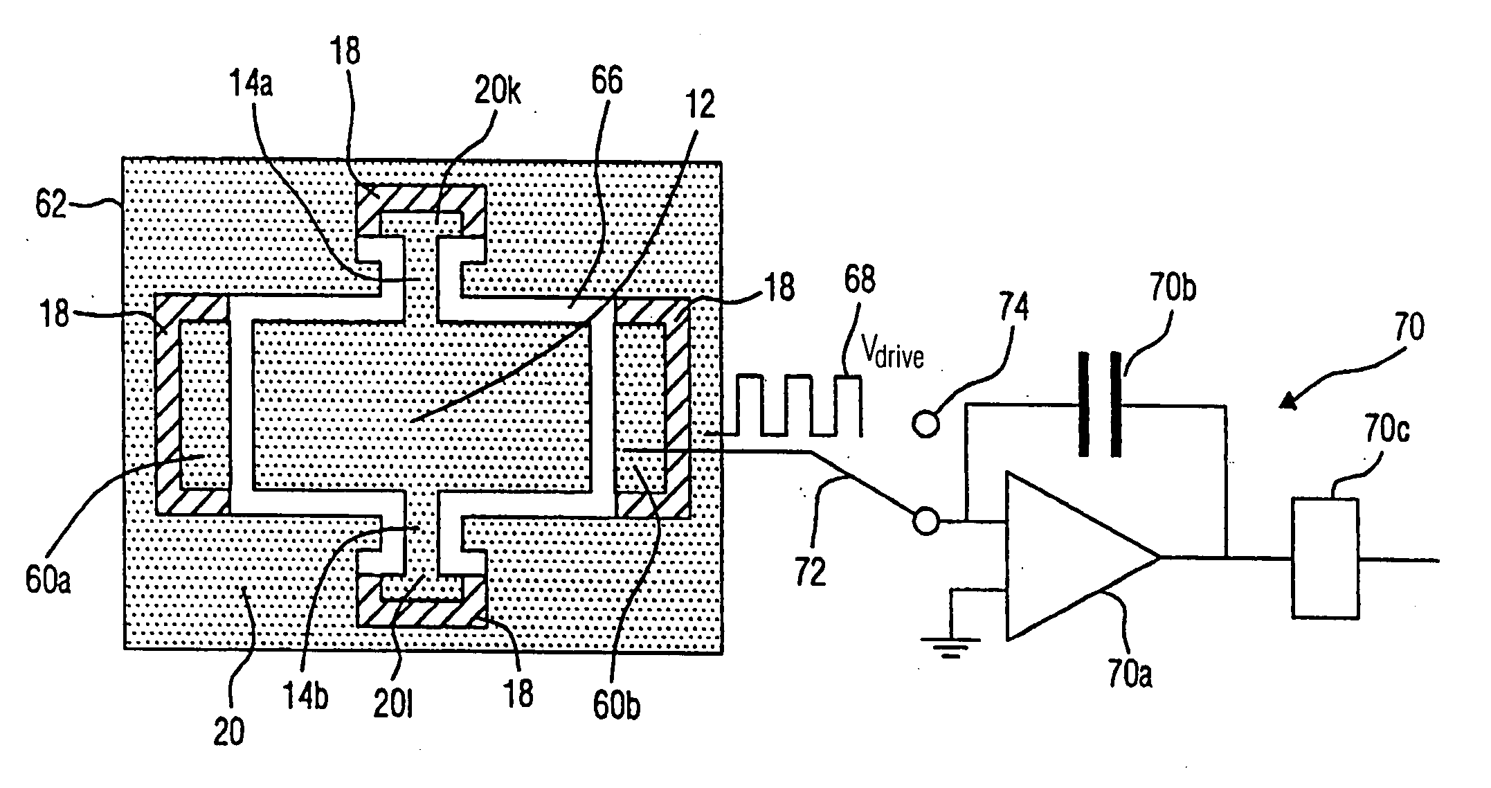
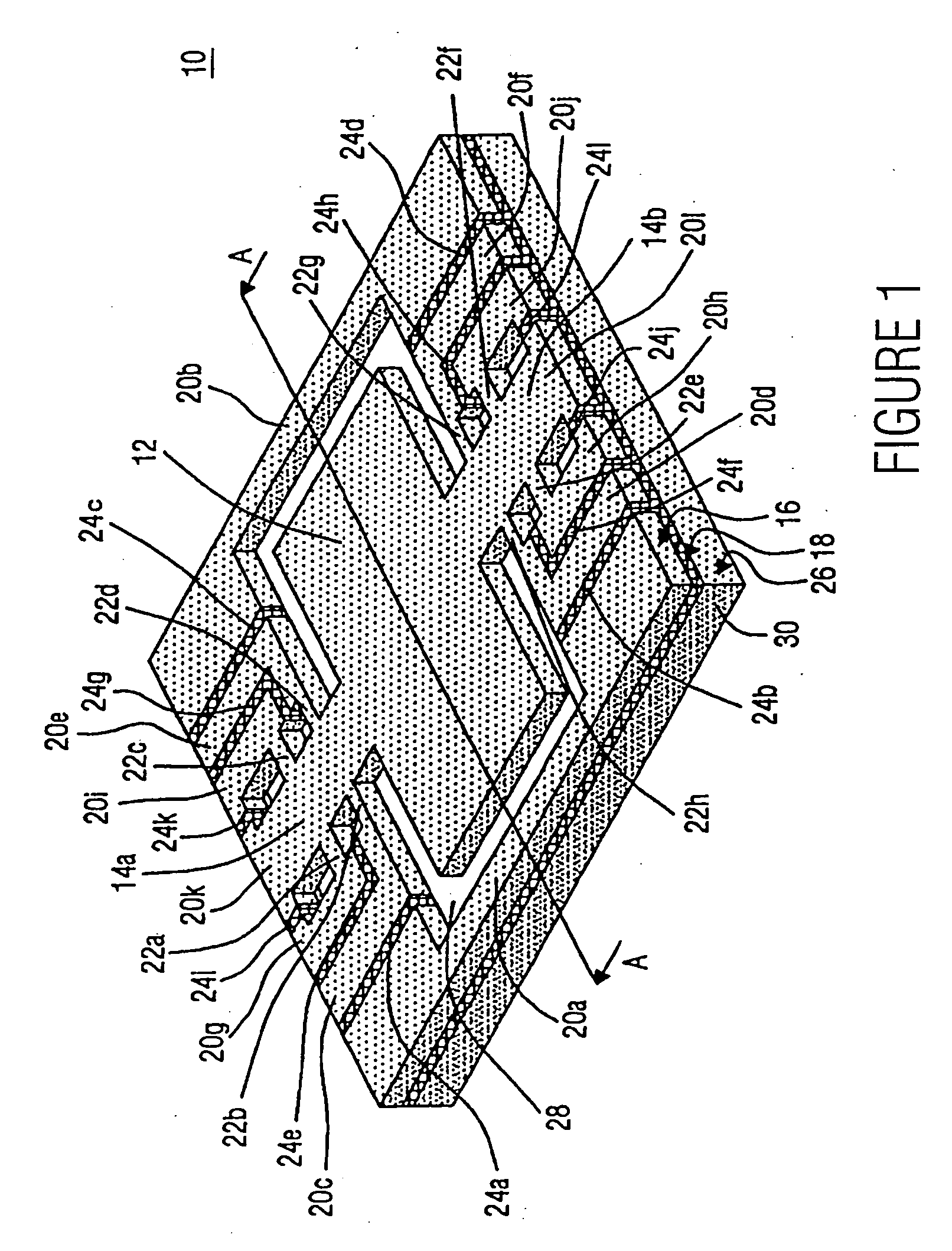
[0030]FIG. 1 shows an embodiment of a vibrating system of a micromechanical element, which is generally indicated by 10, where the present invention may be implemented, as will be explained subsequently. The micromechanical element 10 of the present embodiment represents a micromechanical mirror as is, for example, employed in micro-scanners to deflect a modulated light beam having a predetermined set frequency to move the light beam back and forth in an image field with the set frequency, whereby an image is generated on the image field by the modulated light spot moved on the image field. It is, however, pointed out that the present invent...


PUM


Abstract

A micromechanical element described includes a vibrating system having a vibrating body and an elastic suspension by means of which the vibrating body is suspended to be able to vibrate, and an adjuster for adjusting a resonant frequency of the vibrating system by applying a voltage difference between at least one part of the vibrating body and at least one stationary electrode.

Description

CROSS-REFERENCE TO RELATED APPLICATION [0001] This application is a continuation of copending International Application No. PCT / EP03 / 03943, filed Apr. 15, 2003, which designated the United States and was not published in English, and is incorporated herein by reference in its entirety. BACKGROUND OF THE INVENTION [0002] 1. Field of the Invention [0003] The present invention relates to micromechanical elements having a vibrating system and, in particular, to adjusting the vibrational frequency of the vibrating system. [0004] 2. Description of the Related Art [0005] Micromechanical elements having vibrating systems are employed both in micromechanical sensor and in micromechanical actuators. The vibrating system including a vibrating body and an elastic suspension comprises a natural or resonant frequency. In many applications, the resonant frequency of the vibrating system must correspond to a fixed predetermined frequency in order to achieve, using the resonance increase, for exampl...

Claims


Application Information

Patent Timeline
Patent Type & Authority Applications(United States)
IPC IPC(8): H02K33/00H02N1/00G01C19/5642G02B26/08H03H9/02H03H9/24
CPCG01C19/5642G02B26/0833G02B26/0841H02N1/006H03H9/02409H03H9/2457H03H2009/02511
Inventor DRABE, CHRISTIANWOLTER, ALEXANDERSCHENK, HARALD
Owner FRAUNHOFER GESELLSCHAFT ZUR FOERDERUNG DER ANGEWANDTEN FORSCHUNG EV
Why Eureka
Try Eureka