
Apparatus for manufacturing particles using corona discharge and method thereof

a technology of apparatus and particles, applied in the field of apparatus and methods for manufacturing particles, can solve the problems of contaminating the environment, low collection efficiency of collected particles, and inability to control the size of collected particles, and achieve the effect of high collection efficiency

Inactive Publication Date: 2006-04-06
AHN KANG HO +2
View PDF4 Cites 0 Cited by
  • Summary
  • Abstract
  • Description
  • Claims
  • Application Information

AI Technical Summary

Benefits of technology

[0004] An object of the present invention is to provide an apparatus and method for manufacturing particles using corona discharge, in which very high collecting efficiency can be obtained.
[0005] Another object of the present invention is to provide an apparatus and method for manufacturing particles using corona discharge, in which sizes of the particles can be controlled.

Problems solved by technology

However, in conventional methods for manufacturing the particles, there are some disadvantages in that their collecting efficiency is very low, and in that sizes of the collected the particles cannot be controlled.
In addition, there are problems in that most of the particles that are not collected cannot be recovered, and in that since the particles that have been recovered are mainly metal oxide, they may contaminate the environment.
Especially, in the conventional method for manufacturing the particles by using the filter, there is a trouble in that the filter should be frequently replaced due to serious contamination of the filter.

Method used


Image

  • Apparatus for manufacturing particles using corona discharge and method thereof
  • Apparatus for manufacturing particles using corona discharge and method thereof
  • Apparatus for manufacturing particles using corona discharge and method thereof

Examples


first embodiment

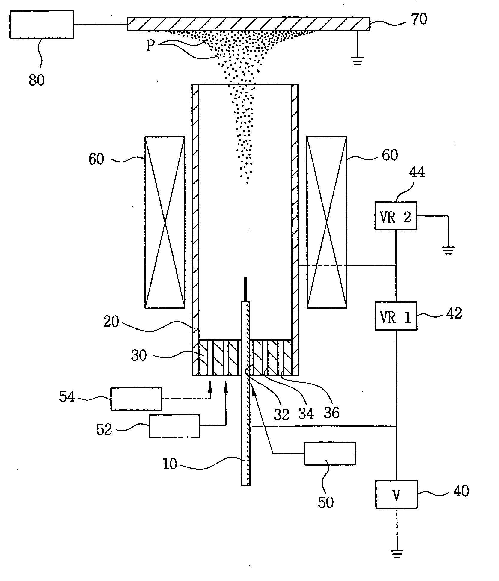
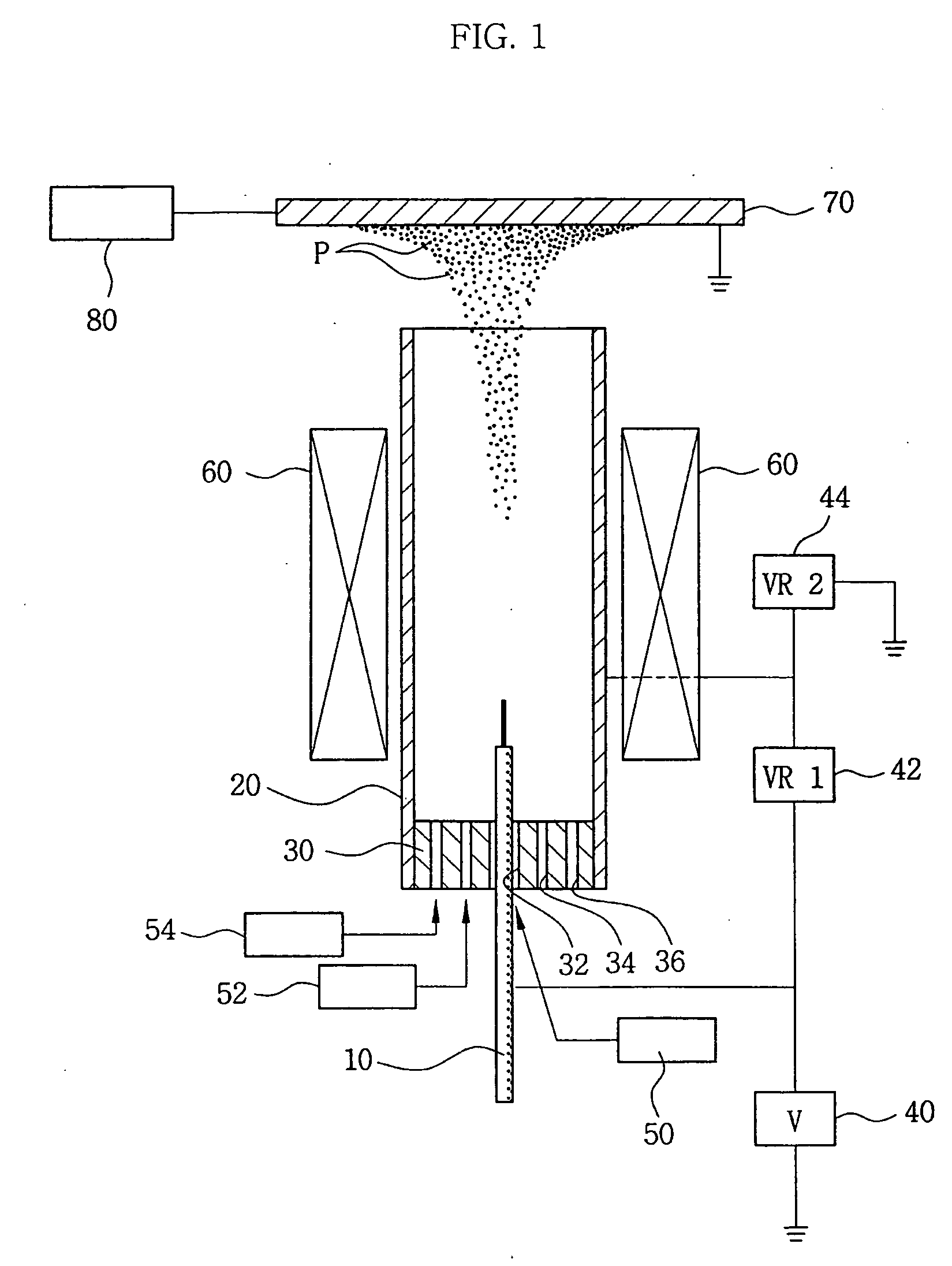
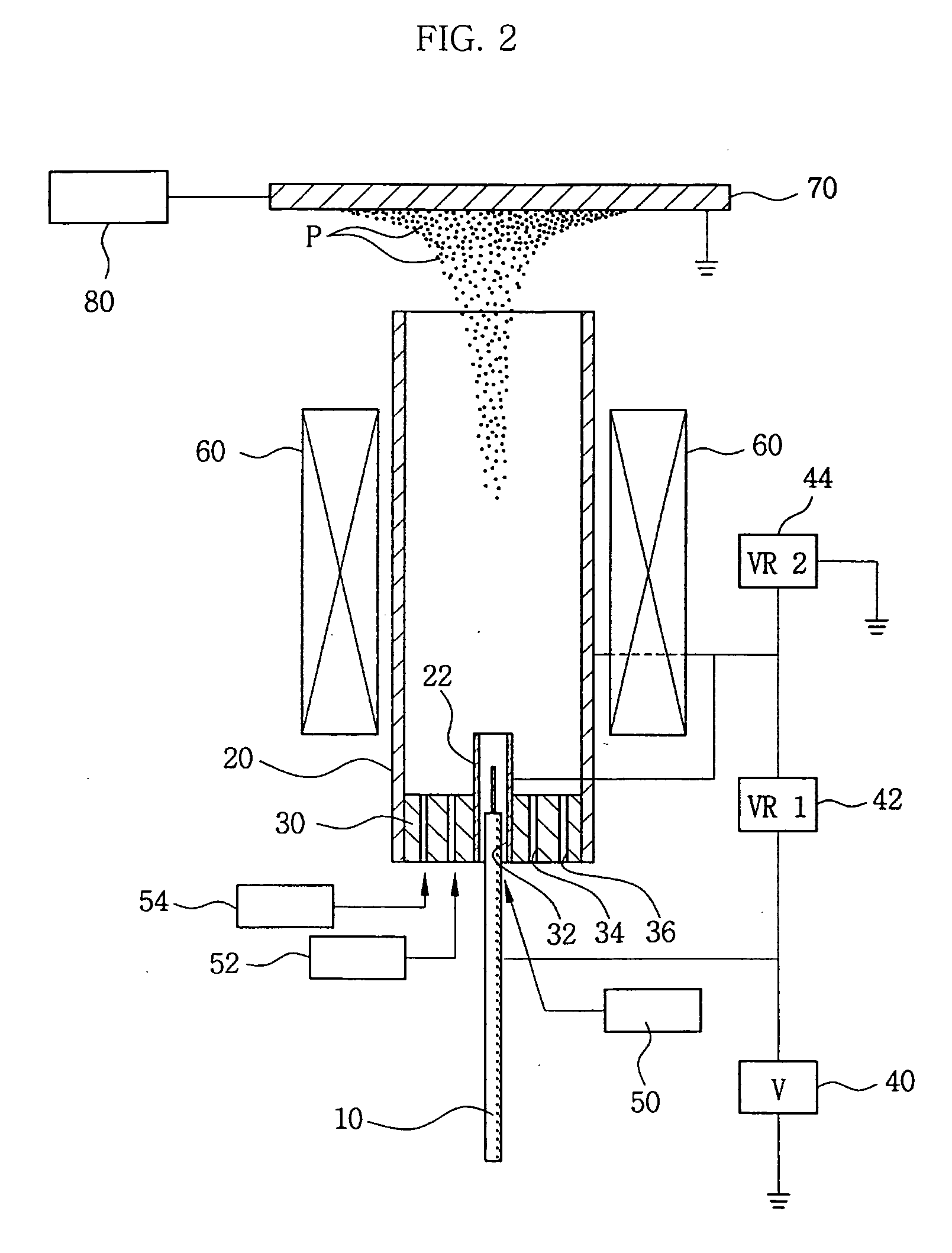
[0026] First, the constitution of an apparatus for manufacturing particles according to the present invention will be explained with reference to FIG. 1. Referring to FIG. 1, a needle type discharge electrode 10 is positioned within a guide duct 20. As well known, when a high voltage is applied to the discharge electrode 10, a lot of ions are generated around the discharge electrode 10 by the corona discharge as electric discharge. In order to prevent the ions generated by corona discharge from adhering to an inside wall of the guide duct 20, a voltage is applied to the guide duct 20 to have the same polarity as the voltage applied to the discharge electrode 10.

[0027] Thus, a high voltage is applied to the discharge electrode 10 from a power supply 40, while a low voltage having the same polarity as the voltage applied to the discharge electrode 10 is applied to the guide duct 20. In order to generate a voltage difference between the discharge electrode 10 and the guide duct 20, a f...

third embodiment

[0039]FIG. 8 represents a first modification of the In order to increase the generation of ions by means of corona discharge around the wire type discharge electrode 12 and to prevent dust substances from adhering to the wire type discharge electrode 12, the present modification includes a guide plate 24 surrounding the discharge electrode 12 so that chemical reaction gases such as CO2 or N2 are supplied by a chemical reaction gas supplying device. In addition, a voltage which has the same polarity and level as the guide duct 20 is applied to the guide plate 24, so that the guide plate 24 guides the flow of the ions generated from the discharge electrode 12 by means of the corona discharge. Meanwhile, oxidation gases or reaction gases or the mixed oxidation gases and reaction gases are supplied between the guide plates 24 by an oxidation gas supplying device 52 or a reaction gas supplying device 54.

[0040]FIG. 9 represents a second modification of the third embodiment. In the second...

second embodiment

[0048] According to the constitution of the second embodiment, in order to assist in generating a lot of ions from the discharge electrode 10 and to prevent chemical reaction from occurring by the strong energy around the discharge electrode 10, the chemical reaction control gases such as CO2 or N2 are supplied to the interior of the first guide duct 21. The reaction gases such as SiCl4 or GeCl4 are supplied between the first guide duct 21 and the second guide duct 23 (S30), and the sheath gases are supplied between the second guide duct 23 and the third guide duct 25. The fuel gases are supplied between the third guide duct 25 and the fourth guide duct 27.

[0049] When fuel gases are discharged from between the third guide duct 25 and the fourth guide duct 27 to the outside, the fuel gases are ignited. Then, the thermal energy is generated by the combustion of the fuel gases. As described in the first embodiment, chemical reactions of the particles discharged from between the first g...


PUM

PropertyMeasurementUnit
voltageaaaaaaaaaa
energyaaaaaaaaaa
distanceaaaaaaaaaa

Abstract

An apparatus and method for manufacturing particles using corona discharge is disclosed. A discharge electrode is provided within a guide duct and reaction gases are supplied into the guide duct. A high voltage is applied to the discharge electrode and a low voltage is applied to the guide duct to generate a voltage difference therebetween. When heat energy is applied to the reaction gases, chemical reactions occur in the gases and particles are made by the chemical reactions. The particles form new particles centering around ions as nuclei which are generated by corona discharge and moves along the guide duct. A collecting plate positioned in front of the guide duct collects the particles.

Description

TECHNICAL FIELD [0001] The present invention relates to an apparatus and method for manufacturing particles, and more particularly, to an apparatus and method for manufacturing particles using corona discharge. BACKGROUND ART [0002] Generally, particles are manufactured by a method of collecting them through a filter or sticking them to a collecting plate after they have been formed by using flames or a furnace. According to this method, metal oxide such as SiO2 or Fe2O3 having ultrahigh purity are obtained. [0003] However, in conventional methods for manufacturing the particles, there are some disadvantages in that their collecting efficiency is very low, and in that sizes of the collected the particles cannot be controlled. In addition, there are problems in that most of the particles that are not collected cannot be recovered, and in that since the particles that have been recovered are mainly metal oxide, they may contaminate the environment. Especially, in the conventional meth...

Claims


Application Information

Patent Timeline
Patent Type & Authority Applications(United States)
IPC IPC(8): H02H1/04B03C3/38B01J19/08B03C3/41C01G1/00C01G1/02C01G49/02H05H1/24
CPCB01J12/002B01J19/088B01J2219/00146B01J2219/0811B01J2219/083B01J2219/0849B01J2219/0871B01J2219/0883B01J2219/0894B03C3/38B03C3/41C01G1/00C01G1/02C01G49/02H05H1/24B03C2201/10H05H1/471
Inventor AHN, KANG-HOAHN, JEONG-HOAHN, SANG-HYUN
Owner AHN KANG HO
Learn More