Complementary-pair equalizer

a technology of equalizer and pair, applied in the field of signal modification, can solve the problems of increasing the rejection of undesired signals, and achieve the effects of increasing ratio, increasing energy, and decreasing energy

Inactive Publication Date: 2006-04-06
SCHWARTZ STEPHEN R +2
View PDF22 Cites 47 Cited by
  • Summary
  • Abstract
  • Description
  • Claims
  • Application Information

AI Technical Summary

Benefits of technology

[0007] In the example of the steam radiator and chamber orchestra above, a second signal may be supplied by a second microphone placed far from the offending steam sound. This may be in an odd corner of the room, which may not be good for the overall sound of the music—this second spot needs only to have an increase in ratio of desired sound (music) to undesired sound (steam hiss) in the frequency range of the undesired sound, as compared to the first signal in the same frequency range. As the apparatus is adjusted to decrease the energy of the original signal's offending frequency band, where the amount of unwanted noise is high, it simultaneously increases the energy in the same band of the second signal, where the amount of unwanted noise is low. The summing of the signals will provide an increase in the reduction of the unwanted noise, while maintaining the fidelity of the original music.

Problems solved by technology

The first filtered signal and second ‘inverse-filtered’ signal are then summed, which may result in a signal similar in accuracy to the first signal path alone, and may also have an increase in the rejection of the undesired signal.

Method used


Image

  • Complementary-pair equalizer
  • Complementary-pair equalizer
  • Complementary-pair equalizer

Examples


Embodiment Construction

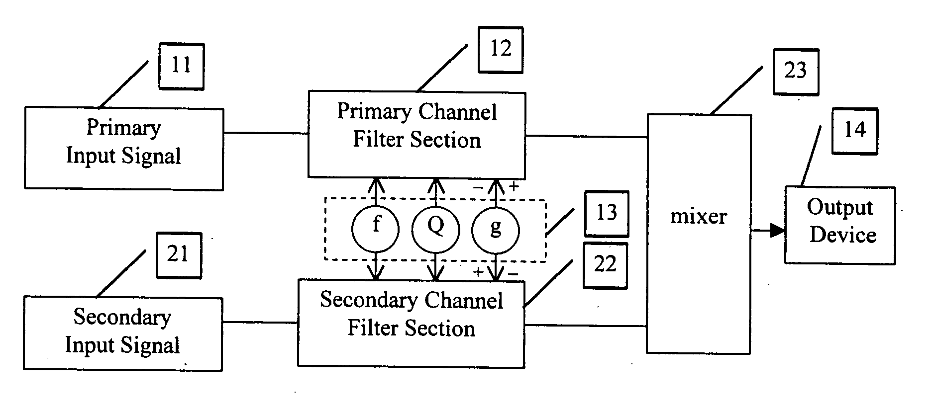
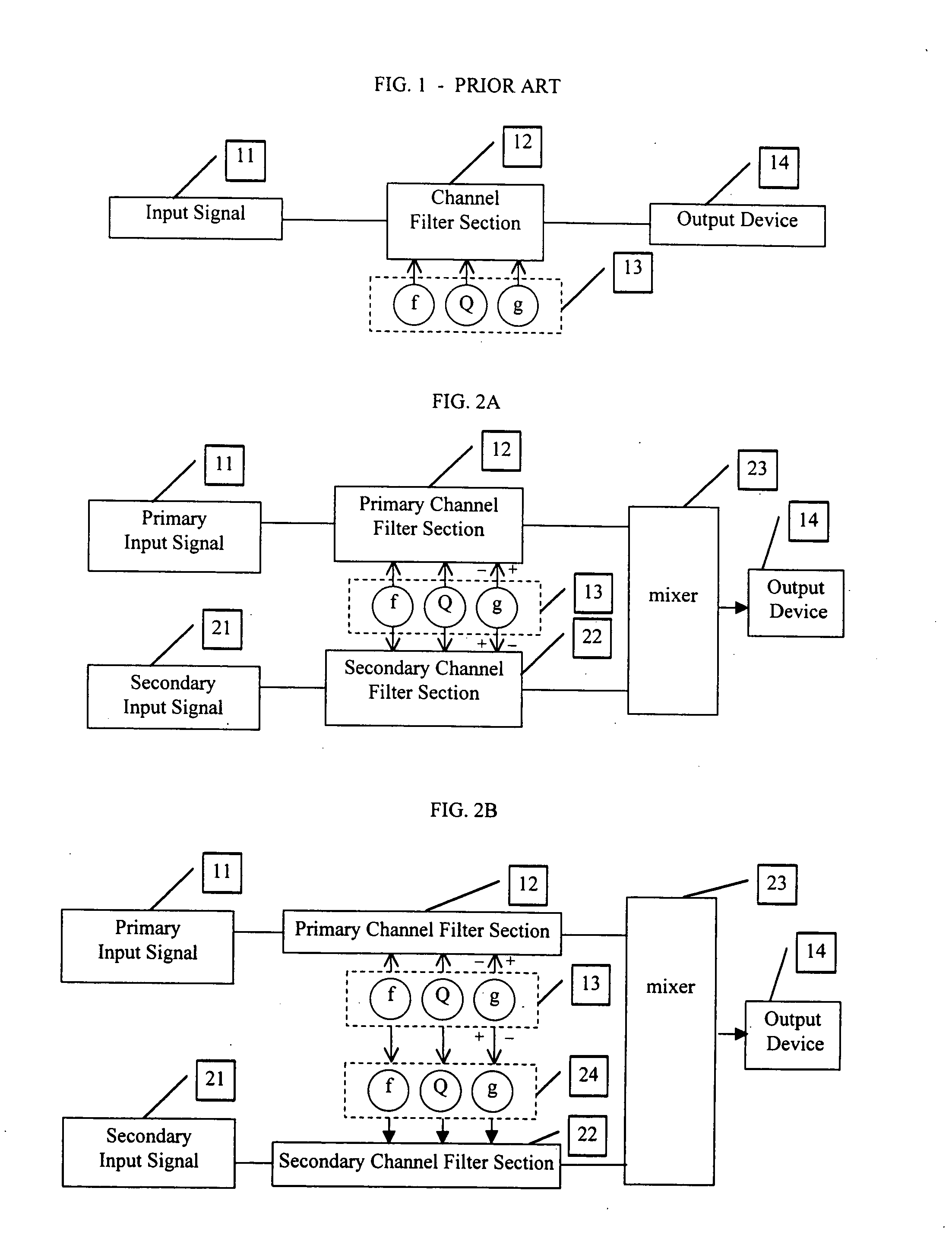
[0021]FIG. 1 is a general block diagram of a typical audio equalizer as is known in the art. The type shown here is for a single channel of a fully-parametric equalizer. An input signal 11 is fed to a filter circuit 12 whose parameters are determined by the controls ‘f’, ‘Q’ and ‘g’13. Control ‘f’ determines the center frequency of the affected area. Control ‘Q’ determines the bandwidth of the affected area. Control ‘g’ reduces (by convention, counterclockwise from center position) or increases (clockwise from center position) the signal in the area determined by the settings of ‘f’ and ‘Q’. At the center setting of ‘g’, where there is no increase or decrease of signal, the settings of ‘f’ and ‘Q’ have no effect. The final signal may be sent to an output device 14. For some discussion below, it is helpful to refer to input signal 11 and filter circuit 12 as the PRIMARY input signal and filter circuit.

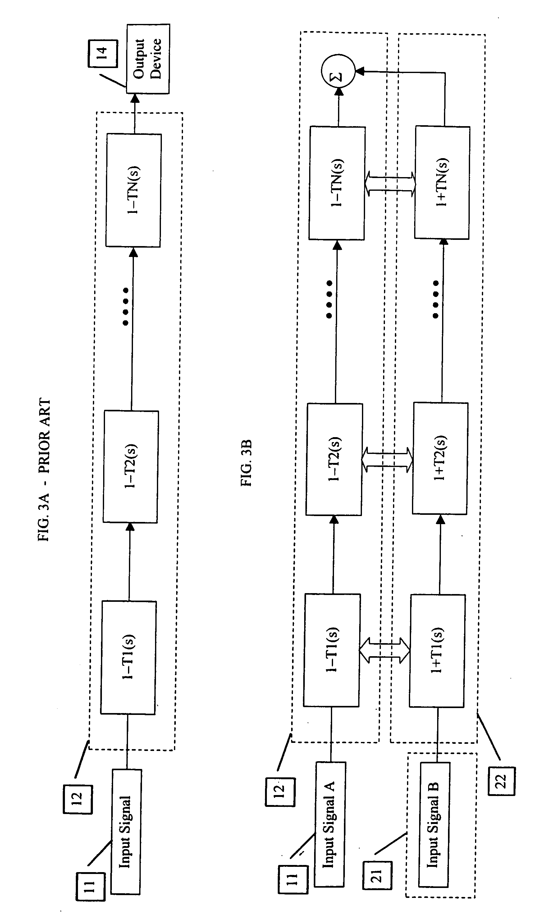
[0022] There are two basic categories of filters. The first category is that of th...


PUM


Abstract

A method and apparatus are described which reduce the presence of an unwanted signal. According to one embodiment, a first signal is provided from a desired location that includes an unwanted signal while a second signal is provided from an alternate location (e.g., one where the unwanted signal is less of a proportion of the total signal). The first and alternate signals are provided to respective signal processors. A level for a selected frequency band of the first and alternate signals is adjusted so that an increase in one results in a decrease in the other. Doing so allows the frequency band that includes the unwanted signal to be reduced in the desired first signal and filled in with a similar frequency band from the alternate signal.

Description

[0001] This is a continuation of application Ser. No. 09 / 344,299 filed 24 Jun. 1999, the content of which is incorporated herein by reference.BACKGROUND OF THE INVENTION [0002] The present invention deals with the field of signal modification. In particular, it deals with a method and device / s for the selection of frequency portions of at least two versions of a signal which are summed to create a signal which may be superior to, and / or avoid problems found in,one or more of the source signals. [0003] When transducing audio signals to electrical signals, it is common to eliminate undesireable elements by the process of somehow filtering or equalizing those signals. For example, where a musical performance is recorded in a concert hall, problem noises are often caused by the noises made by lights, HVAC systems and blowers, etc. Some of these sounds may be more pronounced at some places than at others. It is common for there to be certain places where the overall sound is most desirea...

Claims


Application Information

Patent Timeline
Patent Type & Authority Applications(United States)
IPC IPC(8): H04B15/00
CPCH04S1/00
Inventor SCHWARTZ, STEPHEN R.OSMAND, JOHN H.KULASH, DAMIAN
Owner SCHWARTZ STEPHEN R
Why Eureka
Try Eureka