Method for polarization-based intrusion monitoring in fiberoptic links

a technology of intrusion monitoring and fiberoptic links, applied in transmission monitoring, transmission monitoring/testing/fault-measurement systems, electrical equipment, etc., can solve the problem of random and unpredictable slow time-varying birefringence components

Inactive Publication Date: 2006-04-06
THE BOARD OF RGT UNIV OF OKLAHOMA
View PDF11 Cites 24 Cited by
  • Summary
  • Abstract
  • Description
  • Claims
  • Application Information

AI Technical Summary

Benefits of technology

[0016] Further, the polarization reference frame is recalibrated. The calibration symbols of the transmitted expanded data stream (i.e., the three known-launched SOPs and the three measured-received SOPs) are utilized to determine a new or “revised” polarization reference frame in the manner describe above. The new polarization reference frame can then be used when the above described steps are repeated for a subsequently transmitted expanded data stream. As discussed above, by continually or periodically revising or “updating” the polarization transformation function of the fiberoptic link, the slow time-varying birefringence component is tracked and better compensated for. Also, the step of recalibrating the polarization reference frame allows adaptation for desired or tolerated environmental changes in the fiberoptic link so as to provide for continuing transmission of data and monitoring.

Problems solved by technology

There is also a slow time-varying birefringence component that is considered to be random and unpredictable.

Method used


Image

  • Method for polarization-based intrusion monitoring in fiberoptic links
  • Method for polarization-based intrusion monitoring in fiberoptic links
  • Method for polarization-based intrusion monitoring in fiberoptic links

Examples


Embodiment Construction

[0028] Presently preferred embodiments of the invention are shown in the above-identified figures and described in detail below. In describing the preferred embodiments, like or identical reference numerals are used to identify common or similar elements. The figures are not necessarily to scale and certain features and certain views of the figures may be shown exaggerated in scale or in schematic in the interest of clarity and conciseness.

I. Introduction

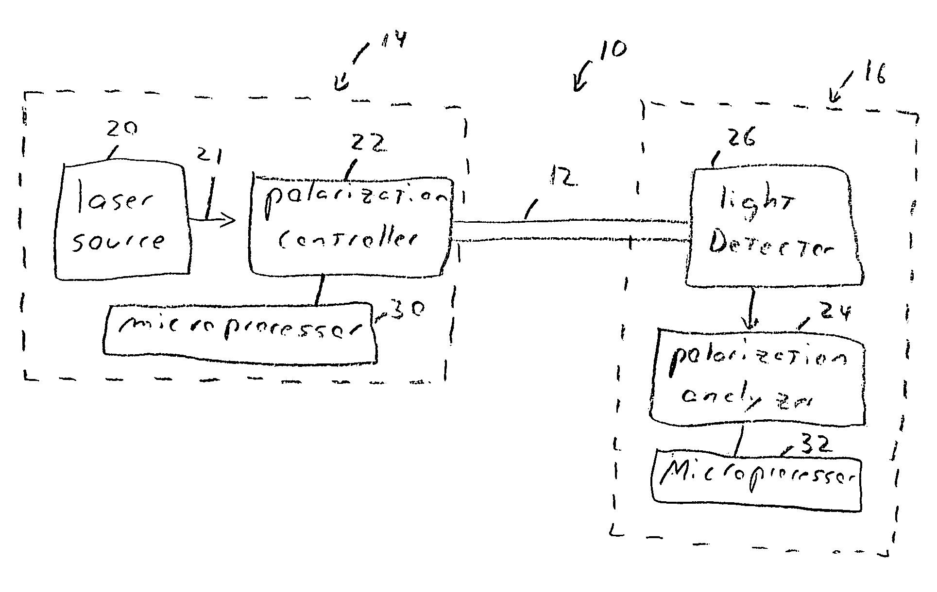
[0029] Referring now to the drawings and in particular to FIG. 7A, a fiber optic communication system 10 constructed in accordance with the present invention is shown. The fiber optic communication system 10 uses the polarization of the light signal to enhance the physical security of one or more fiber optic link 12 in optical network(s). In a preferred embodiment, a polarization-shift keying (POLSK) scheme is used to generate an expected pattern of changing states of polarization (SOPs). A deviation from the expected pattern at t...


PUM


Abstract

A fiber optic communication system including a fiber optic link, a transmitter system and a receiver system. The transmitter system includes a laser source producing a light beam, and a polarization controller receiving the light beam and providing an expected pattern of changing states of polarization to the light beam to output light signals into the fiber optic link to cause the expected pattern of changing states of polarization to be transmitted along the fiber optic link. The receiver system is provided with a polarization analyzer, and a light detector. The light detector receives the light signals transmitted by the transmitter, and forwards data indicative of the light signals to the polarization analyzer. The polarization analyzer analyzing the data with an inverse polarization reference frame and generates an alert based on deviations of the data from the expected pattern of changing states of polarization.

Description

CROSS-REFERENCE TO RELATED APPLICATIONS [0001] The present patent application claims priority to the provisional patent application identified by U.S. Serial No. 60 / 616,328 which was filed on Oct. 6, 2004. The entire content of the provisional patent application identified by U.S. Serial No. 60 / 616,328 is hereby incorporated herein by reference.STATEMENT REGARDING FEDERALLY SPONSORED RESEARCH OR DEVELOPMENT [0002] Not Applicable. BACKGROUND OF THE INVENTION [0003] Optical communications is a fast advancing technology. As the transmission of information using fiberoptic cables increases, security risks become of growing concern, especially if military or other highly sensitive information is being transmitted. One prior art method of security for optical communications includes manual surveillance. Another prior art method includes installing fiberoptic cables in pressurized pipes, and then generating an alert whenever pressure monitors detect a variation in the pressure beyond some ...

Claims


Application Information

Patent Timeline
Patent Type & Authority Applications(United States)
IPC IPC(8): H04B10/00
CPCH04B10/85
Inventor MACDONALD, GREGORY G.SLUSS, JAMES J. JR.
Owner THE BOARD OF RGT UNIV OF OKLAHOMA
Why Eureka
Try Eureka