Floor tile debris interceptor and transition plenum in a nuclear power plant

Inactive Publication Date: 2006-04-13
GENERAL ELECTRIC CO
View PDF22 Cites 17 Cited by
  • Summary
  • Abstract
  • Description
  • Claims
  • Application Information

AI Technical Summary

Benefits of technology

[0008] Accordingly, the present invention provides a method and apparatus to reduce the debris capturing burden on existing sump strainers or replacement sump strainers by serving as both multiple inlets for the sump strainer and a norma

Problems solved by technology

The fallen debris can accumulate on the containment sump strainers and affect the volumetric flow rate of cooling water delivered to the reactor and containment, which in turn, could lead to reactor core overheating.
However, sump strainers tend to become clogged by large amounts debris due to small strainer size.
The high entrance velocities may draw more solid debris into contact with the sump strainer causing the portions of the sump strainer experiencing the high entrance velocities to experience higher head loss.
This process continues until the entire sump strainer has collected debris in varying q

Method used


Image

  • Floor tile debris interceptor and transition plenum in a nuclear power plant
  • Floor tile debris interceptor and transition plenum in a nuclear power plant
  • Floor tile debris interceptor and transition plenum in a nuclear power plant

Examples


Embodiment Construction

[0035] It should be noted that these Figures are intended to illustrate the general characteristics of methods and systems of exemplary embodiments of this invention, for the purpose of the description of such exemplary embodiments herein. These drawings are not, however, to scale and may not precisely reflect the characteristics of any given embodiment, and should not be interpreted as defining or limiting the range of values or properties of exemplary embodiments within the scope of this invention. For example, the relative dimensions and size of frame tubes and perforated tiles may be reduced or exaggerated for clarity. Like numerals are used for liked and corresponding parts of the various drawings.

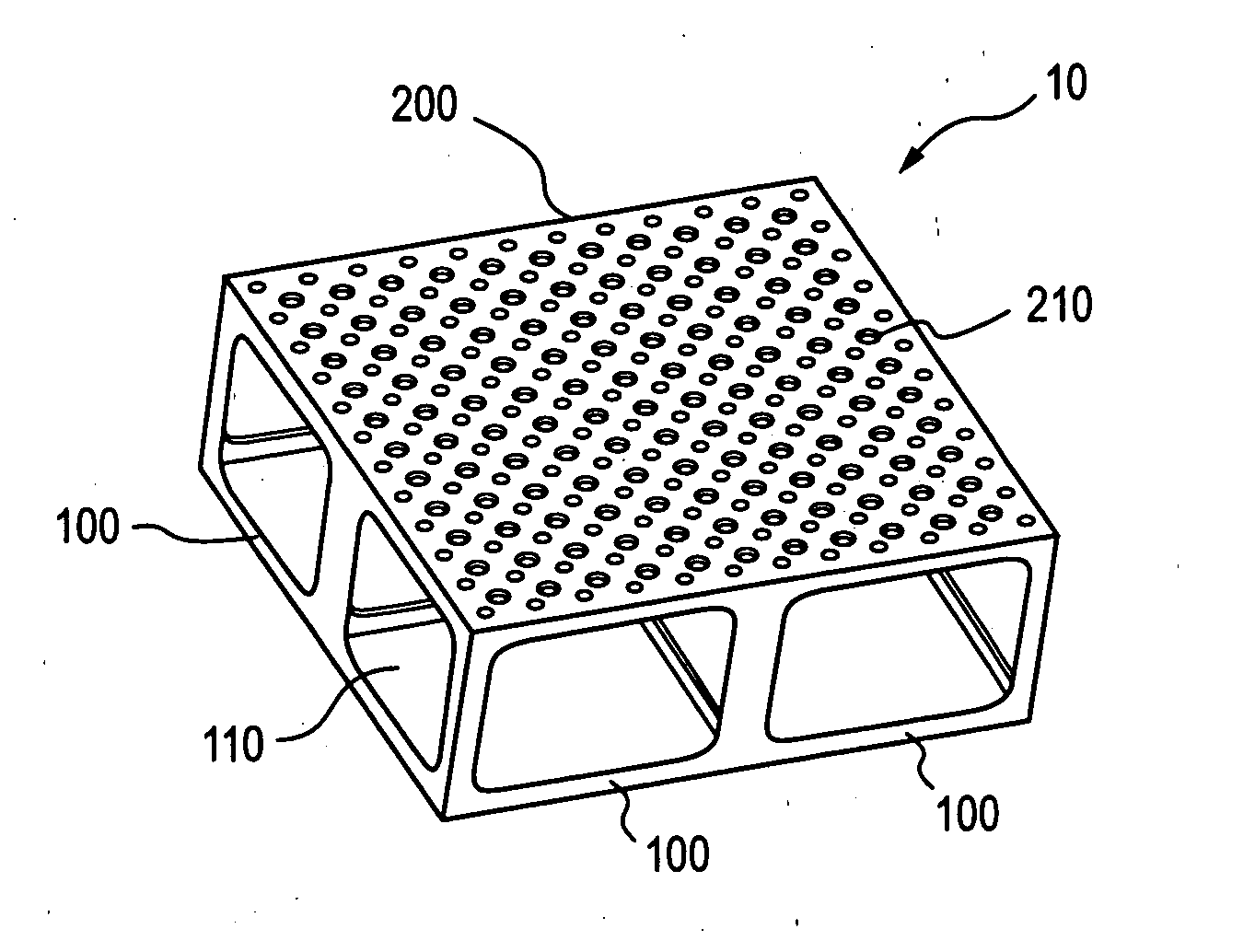
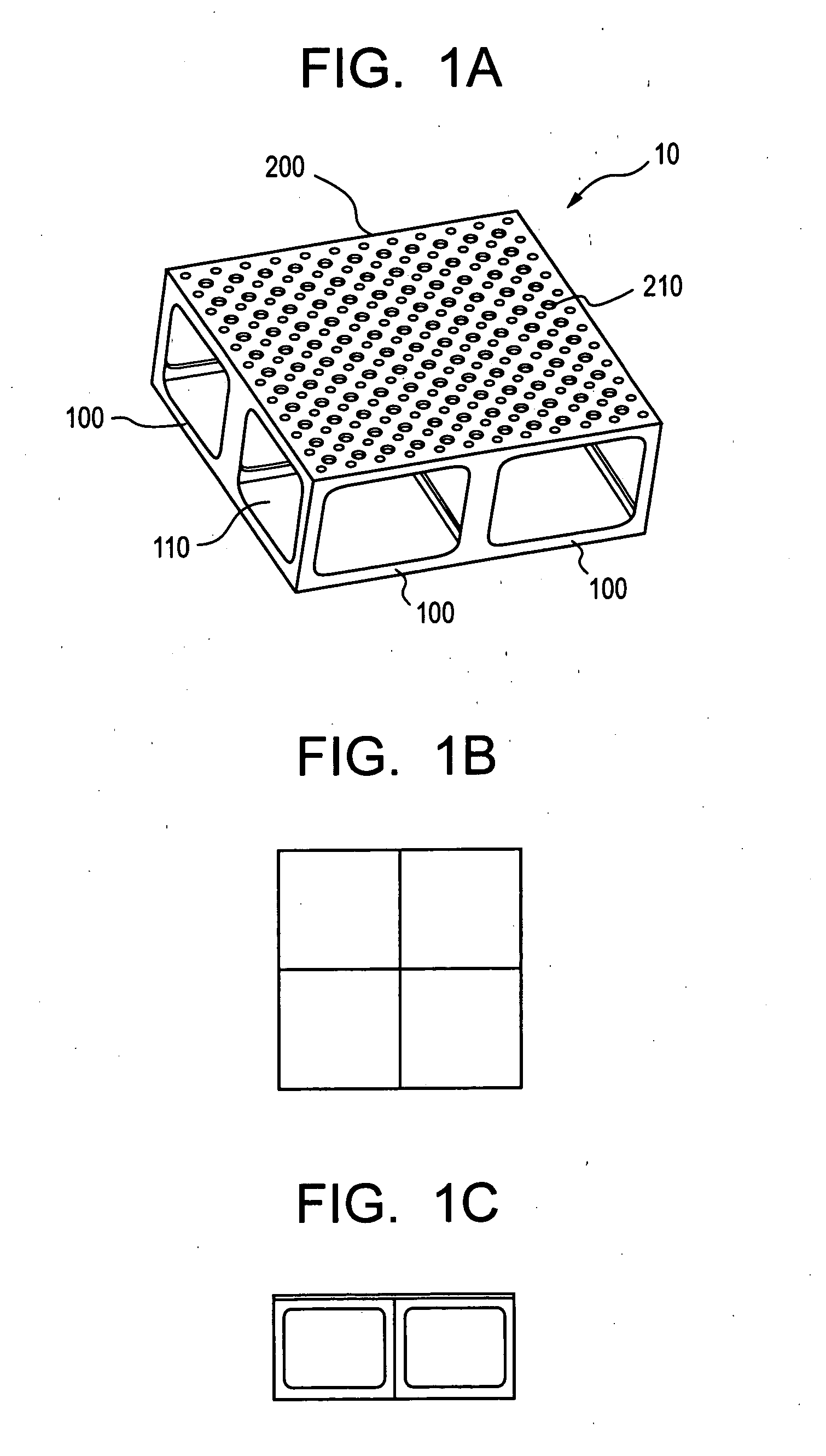
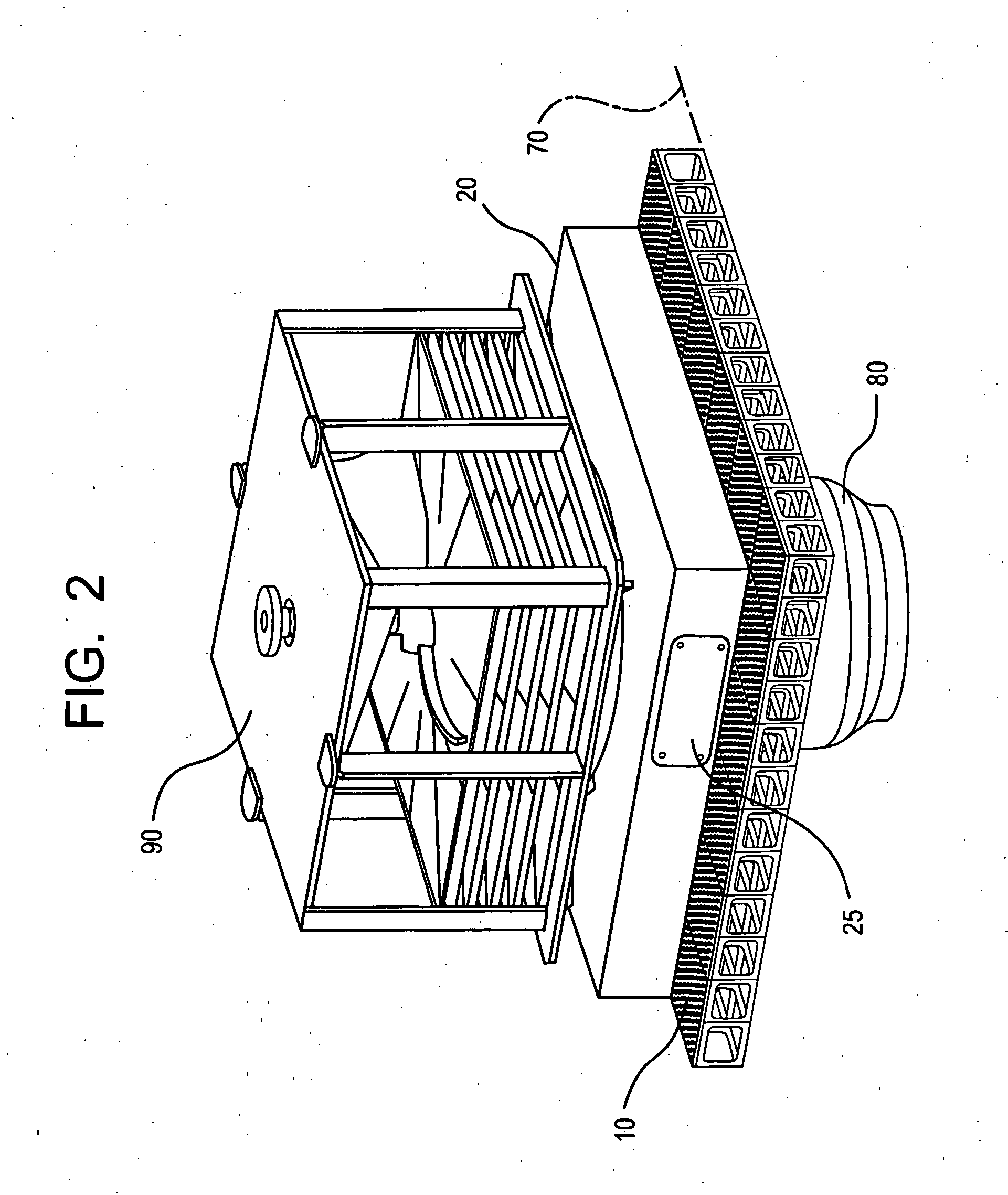
[0036] A flooring system in accordance with the invention may be designed to serve as both multiple inlets for the sump strainer and a normal floor space as now exists in a power plant. Further, the flooring system may disperse collected debris fallen into the containment area so as ...


PUM

PropertyMeasurementUnit
Lengthaaaaaaaaaa
Fractionaaaaaaaaaa
Heightaaaaaaaaaa

Abstract

A flooring system for intercepting debris including at least a plurality of floor tiles with a perforated top surface providing on a top of the plurality of tube frames for intercepting the debris. Each plurality of floor tiles may include a plurality of tube frames in side by side relationship to form a distributed suction area for fluid entrance into tile interiors and for debris interception and capture. The tile interiors of the flooring system may also provide a distributed flow path for fluid flow to a transition plenum. The flooring system may also include a transition plenum for directing a flow path of the fluid from the tiles to a sump, wherein the pumps take suction.

Description

BACKGROUND OF INVENTION [0001] 1. Field of the Invention [0002] This invention relates generally to a flooring system in a nuclear reactor, and more particularly, to a floor tile and transition plenum used in a nuclear power plant containment sump strainer system. [0003] 2. Description of Related Art [0004] A reactor pressure vessel (RPV), such as in a boiling water reactor (BWR) or pressurized water reactor (PWR) nuclear power plant typically will disperse debris to the containment floor following a design basis Loss of Coolant Accident (LOCA) because such reactors have numerous insulated piping systems, and such piping systems are utilized to transport water throughout the reactor system. Nuclear plant design requires inclusion of plant systems for LOCA mitigation. A LOCA results when high pressure pipe ruptures with such force that large quantities of debris, such as pipe thermal insulation, coatings, concrete and other solids may be dispersed onto the containment floor along wit...

Claims


Application Information

Patent Timeline
IPC IPC(8): E04F15/00
CPCG21C9/012G21C15/18G21Y2002/207G21Y2002/50G21Y2004/30Y02E30/40Y02E30/00Y02E30/30G21D1/00G21D1/02
Inventor OATES, JAMES HIBBERTFANNING, ALAN WAYNEFREW, BRIAN DOUGLASMATTHEW KOBEL, BRUCE PETERBAGHDADI, IMAD AHMAD
Owner GENERAL ELECTRIC CO
Why Eureka
Try Eureka