Cutting machine and manufacturing system for fixed size sheet

a manufacturing system and cutting machine technology, applied in the direction of metal working apparatus, etc., can solve the problems of short cutting time, inability to recycle cutting waste, and the above technology is limited to cutting work pieces of comparatively small dimensions, so as to achieve short cutting time, high cutting accuracy, and the effect of avoiding cutting was

Inactive Publication Date: 2006-04-13
TEIPI THERMAL ENG +2
View PDF5 Cites 7 Cited by
  • Summary
  • Abstract
  • Description
  • Claims
  • Application Information

AI Technical Summary

Benefits of technology

[0028] The present invention possessing the above described structure can attain a cutting machine with high accuracy cutting, a short cutting time and without generating cutting waste since the hard plastic sheet is cut with brittle fracture. The present invention can achieve a smoothly cut surface since the hard plastic sheet is cut with brittle fracture in a bent state centered at the cutting position during cutting.

Problems solved by technology

This method does not generate cutting waste that cannot be recycled.
Cutting time is short.
The above technology is limited to cutting work piece of comparatively small dimensions in a process that cuts out the fixed size sheet to obtain a piece of material prior to secondary processing such as vacuum forming or press-forming, and a process to cut out the product after the secondary processing.
However, the following technical problems are encountered during this cutting.
The sheet are flowing so a relative vibration occurs between the cutting machine and the sheet.
However, there is no description in Japanese patent Non-Examined Publication No. 2001-322096 on how to construct the resilient members installed on both sides of the upper and lower blades to resolve these technical problems.

Method used


Image

  • Cutting machine and manufacturing system for fixed size sheet
  • Cutting machine and manufacturing system for fixed size sheet
  • Cutting machine and manufacturing system for fixed size sheet

Examples


Embodiment Construction

[0050] A preferred embodiment of the present invention is described next while referring to the drawings.

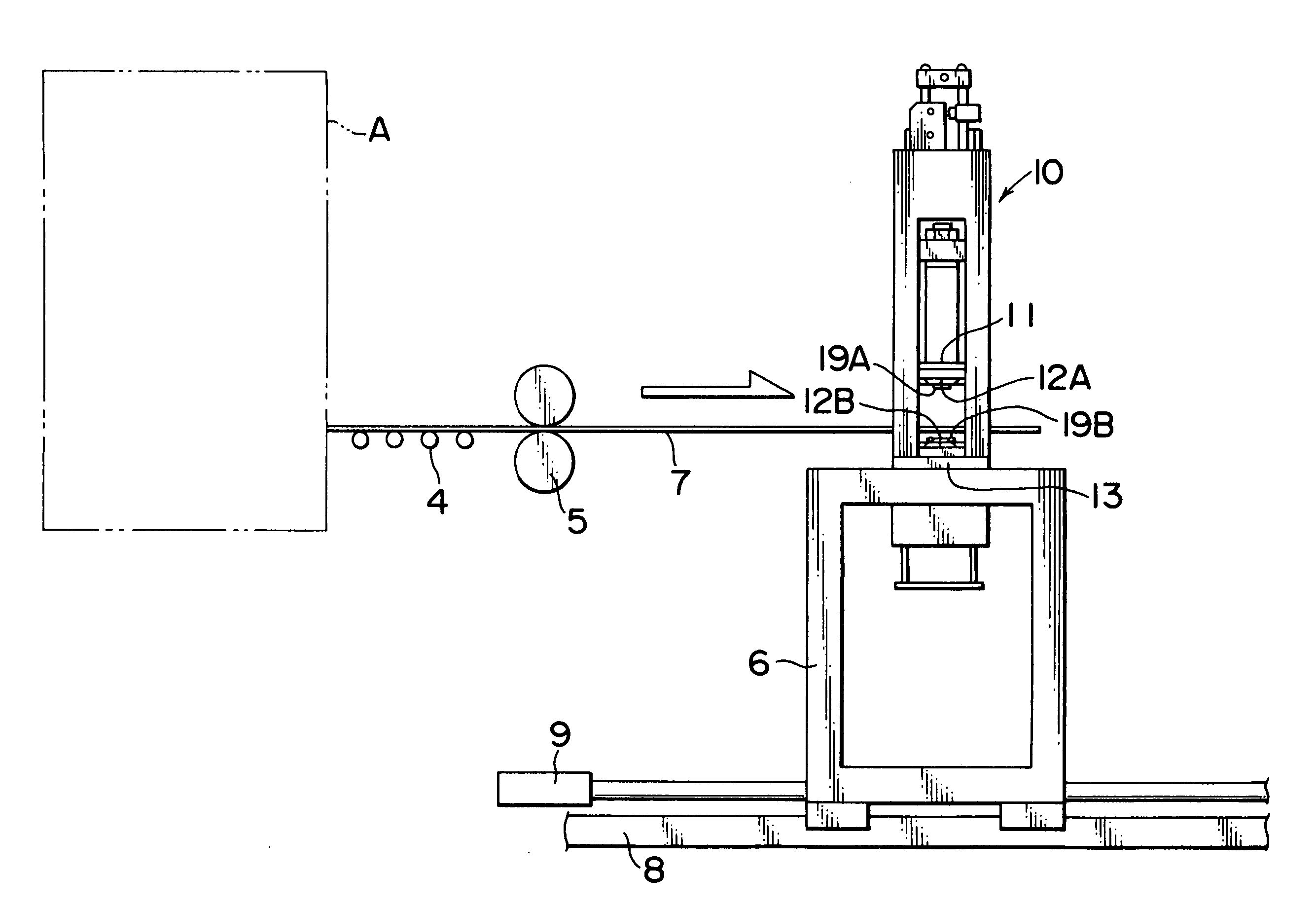
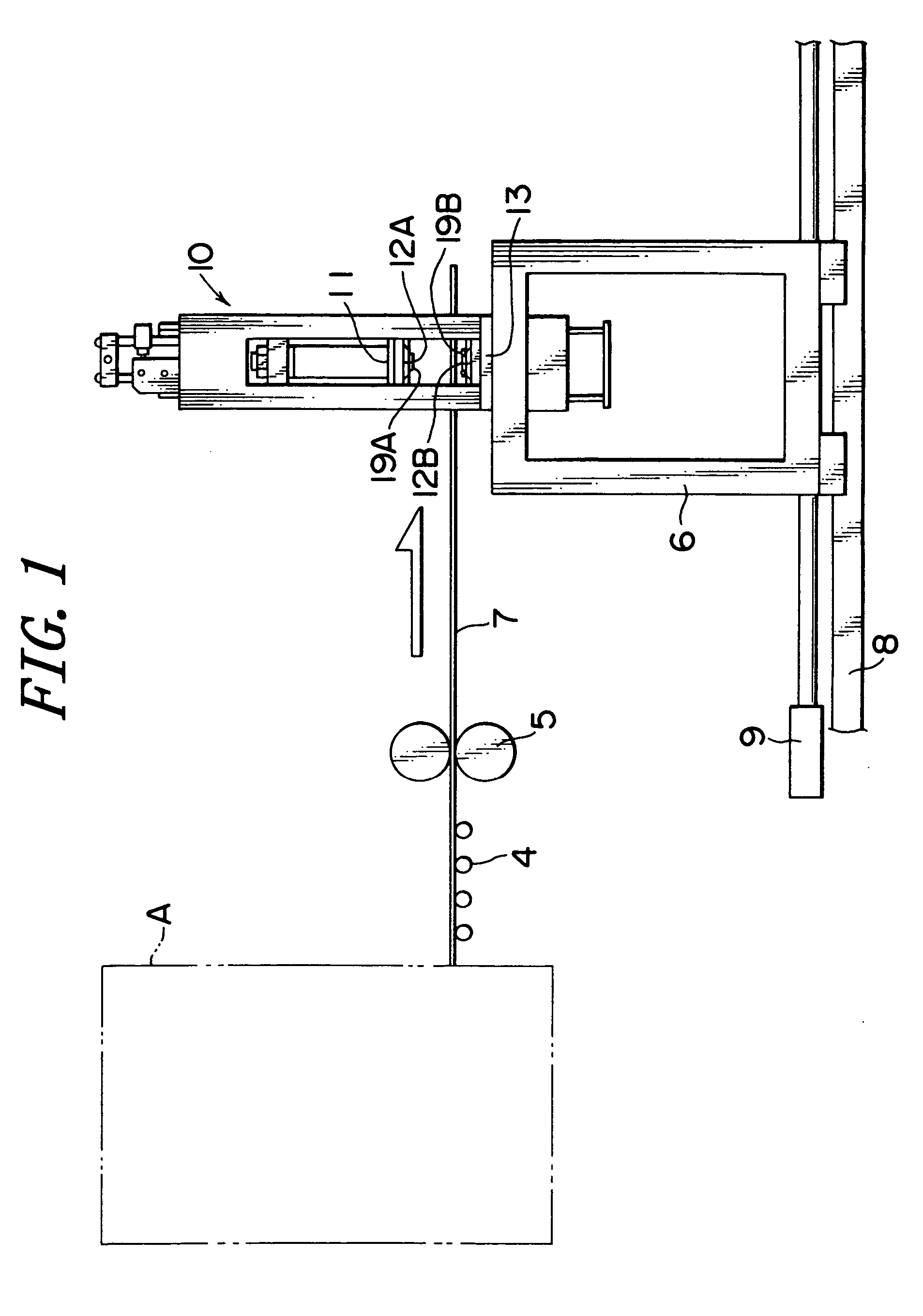
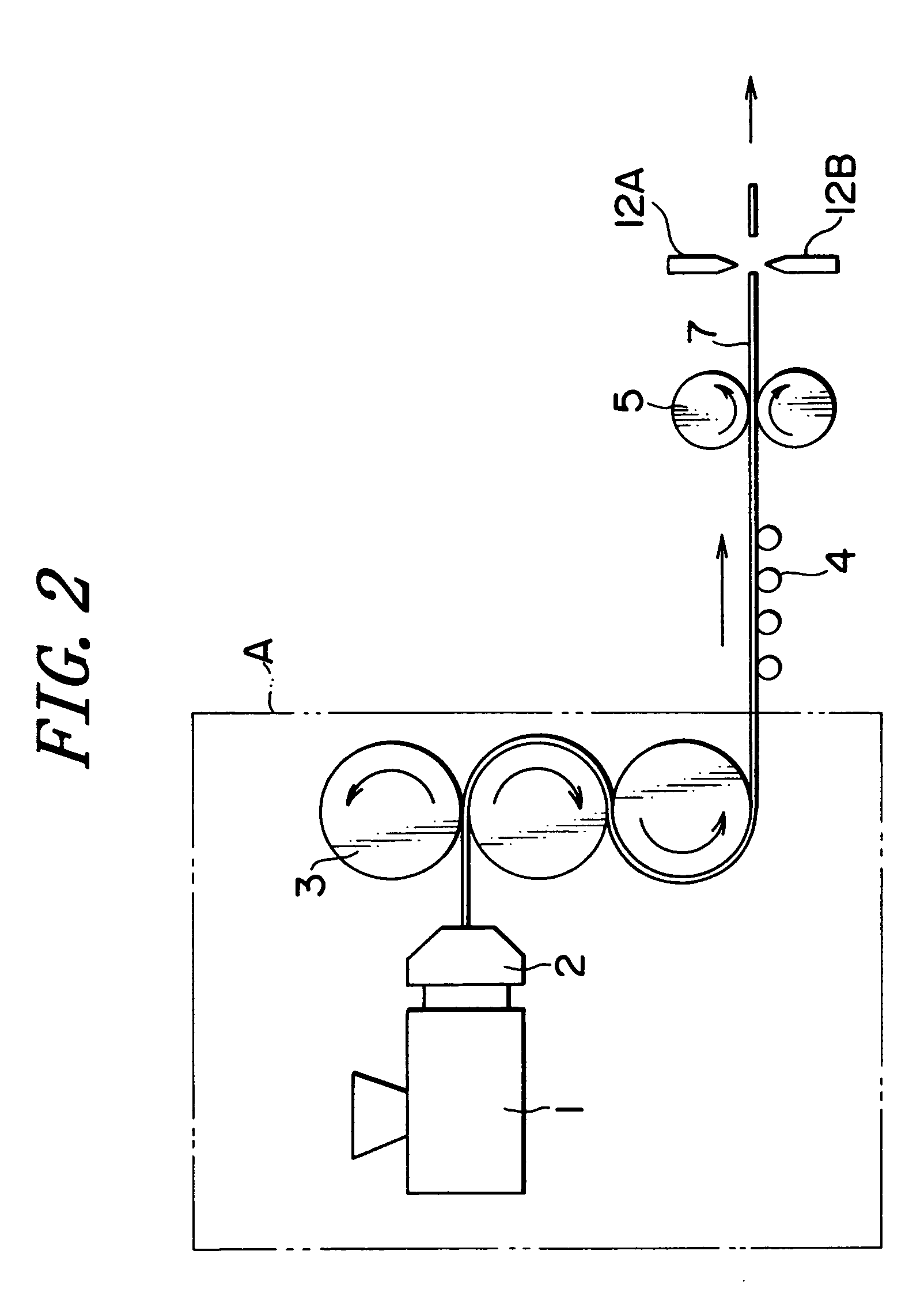
[0051] An extrusion machine 1, a die 2, rolling rolls 3, guide rolls 4, draw rolls 5, and a synchronous cart 6 are arranged in this sequence from the left as shown in FIG. 1 and FIG. 2.

[0052] The extrusion machine 1 heats and melts the thermoplastic resin such as acrylic resin. The thermoplastic resin is heated by the extrusion machine 1 and kneaded in the melted state and fed continuously to the die 2. The heating temperature is the melting temperature of the thermoplastic resin or higher.

[0053] The heated and melted thermoplastic resin is formed into a sheet shape and extruded from the die 2 at a speed for example of 10 to 30 meters per minute. The conventional T die may be utilized as the die 2. The die 2 may extrude a single layer of thermoplastic resin, and may extrude multiple layers of two layers or three layers or more. A continuous single layer sheet can be produced b...


PUM

PropertyMeasurementUnit
widthaaaaaaaaaa
widthaaaaaaaaaa
thicknessaaaaaaaaaa

Abstract

A cutting machine 10 includes an upper blade 12A and a lower blade 12B installed at upper and lower positions, and resilient members 19A, 19B installed on both sides of the blades and protruding more than the blades for supporting a hard plastic sheet 7 during cutting. The resilient members installed on both sides of either of the upper and lower blades include a resilient member at a section near the blade and a resilient member at a section far from the blade, and the hardness of the resilient member at a section near the blade is different from the hardness of the resilient member at a section far from the blade.

Description

BACKGROUND OF INVENTION [0001] 1. Field of Invention [0002] The present invention relates to a cutting machine for cutting a hard plastic sheet, and relates in particular to a cutting machine for cutting a hard plastic sheet such as acrylic sheet with a small percentage of rubber additive, a large width and thin sheet thickness. The present invention further relates to a cutting machine for cutting a continuously flowing hard plastic sheet along the sheet width direction to yield fixed size sheets. [0003] 2. Description of Related Art [0004] One cutting method creates a brittle fracture point by driving cutting blades into both the top and bottom surfaces of a hard plastic sheet, to cut by making the brittle fracture propagate along the direction of the sheet thickness. This technology possesses the following features (Refer to Japanese patent Non-Examined Publication No. 7-285099 and Japanese patent Non-Examined Publication No. 2001-47400). [0005] This method does not generate cutt...

Claims


Application Information

Patent Timeline
Patent Type & Authority Applications(United States)
IPC IPC(8): B26D7/02B29C48/305
CPCB26D1/08B26D1/085B26D7/025B26D7/2614Y10T83/7487Y10T83/9447B26D1/04
Inventor KASHIMOTO, TAKAHISAWATANUKI, YOSHIHIKO
Owner TEIPI THERMAL ENG
Why Eureka
Try Eureka