Smooth finish UV ink system and method

a technology of uv ink and printing system, which is applied in the direction of printing press, printing, duplicate/marking method, etc., can solve the problems of reducing print definition, reducing print definition, and reducing the definition of print, so as to improve surface smoothness and reduce drop spread

Inactive Publication Date: 2006-04-13
ELECTRONICS FOR IMAGING
View PDF26 Cites 121 Cited by
  • Summary
  • Abstract
  • Description
  • Claims
  • Application Information

AI Technical Summary

Benefits of technology

[0006] The present invention provides a printing method, an article printed by the method, and a printing apparatus for carrying out the method, the method including steps of applying an ink-receptive coating to a substrate; printing an actinic radiation-curable ink jet ink over the coating; and curing the printed ink jet ink. The article printed by the method has a ink-receptive coating layer with a cured print. The apparatus for carrying out the method includes a coating station at which the ink-receptive coating is applied to a substrate, an ink jet printhead at which the energy-curable ink jet ink is applied, and a source of actinic radiation for curing the applied ink. The ink may be applied in sufficient amount to achieve a color density comparable to that obtained using other printing processes such as flexographic or gravure printing processes. The ink-receptive coating layer may be of a thickness sufficient to provide improve surface smoothness and / or reduced drop spread relative to an uncoated substrate.

Problems solved by technology

In general, ink containing a substantial amount of organic liquids would produce undesirable emissions during the printing process.
The problem in this case is that flow of the drops also means loss of definition in the print.
Increasing drop spread, however, reduces print definition and increases variation between different substrates because of variation in rate of drop spread on the different substrates.
Further, waiting for drop spread before cure makes the process more time-consuming and less efficient.

Method used


Image

  • Smooth finish UV ink system and method
  • Smooth finish UV ink system and method
  • Smooth finish UV ink system and method

Examples


Embodiment Construction

[0015] The following description of the preferred embodiment(s) is merely exemplary in nature and is in no way intended to limit the invention, its application, or uses.

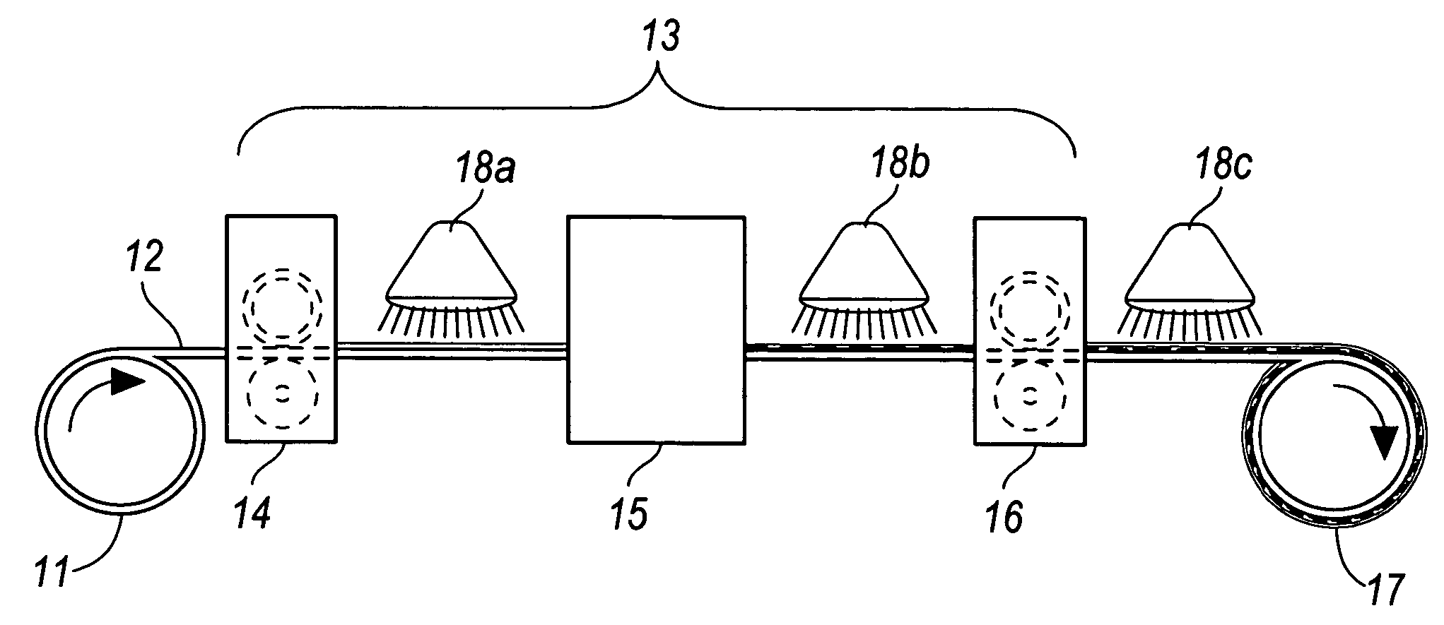
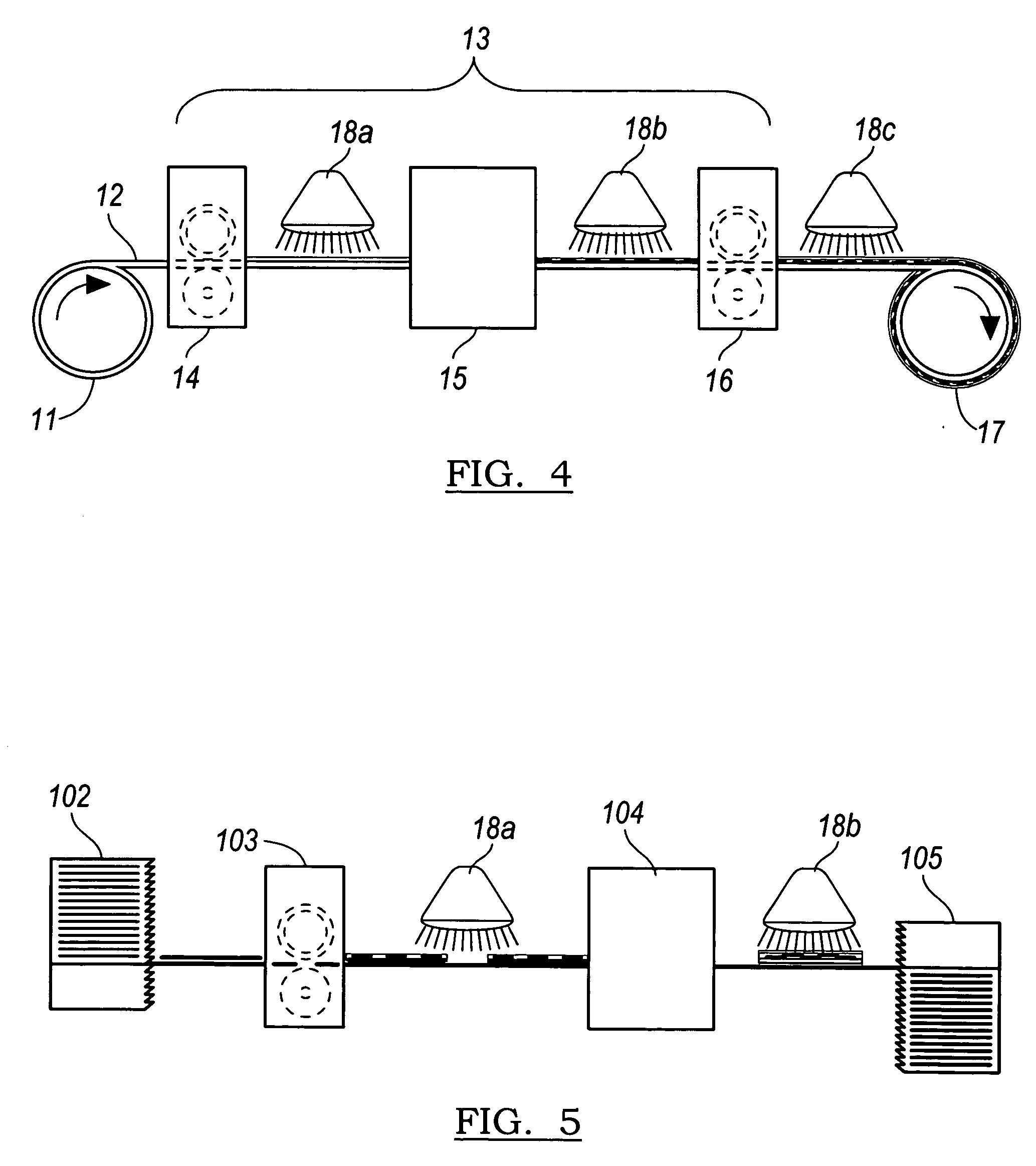
[0016] The inventive system and method provide a means of printing an energy-curable ink with a desirable color density onto nonabsorbent and semi-nonabsorbent substrates. In a first step, a coating receptive to the energy-curable ink is applied to a substrate. The coating may be applied, for example, using flexography gravure coating, bead coating, sloth coating, reverse gravure coating, spray coating, or other known coating methods.

[0017] The ink-receptive coating can be applied over nonporous substrates like metal sheets that may then be formed into cans, plastic, glossy-finished paper or paperboard. Examples of nonabsorbent or semi-nonabsorbent substrates include, without limitation, high gloss paper, satin paper, coated papers, or paperboard; plastic (e.g., polyethylene, polypropylene, or polyester), which may...


PUM

PropertyMeasurementUnit
particle sizeaaaaaaaaaa
viscosityaaaaaaaaaa
particle sizeaaaaaaaaaa

Abstract

A printing method includes steps of applying an ink-receptive coating to a substrate; printing an actinic radiation-curable ink jet ink over the coating; and curing the printed ink jet ink. An article printed by the method has a ink-receptive coating layer with a cured print. An apparatus for carrying out the method includes a coating station at which the ink-receptive coating is applied to a substrate, an ink jet printhead at which the energy-curable ink jet ink is applied, and a source of actinic radiation for curing the applied ink. The ink may be applied in sufficient amount to achieve a color density comparable to that obtained using other printing processes such as flexographic or gravure printing processes. The ink-receptive coating layer may be of a thickness sufficient to provide improve surface smoothness and/or reduced drop spread relative to an uncoated substrate.

Description

FIELD OF THE INVENTION [0001] The invention relates to UV curing ink jet printing systems and methods. BACKGROUND OF THE INVENTION [0002] Inks that cure on exposure to actinic radiation, such as ultraviolet (UV) light or electron beams, have been used in many applications. Gravure, flexographic, and ink jet inks that cure by actinic radiation are all known. Ink jet inks must have a very low viscosity, typically less than about 20 centipoise at the jetting temperature. One way to achieve this low viscosity is by including a substantial amount of organic liquids. In general, ink containing a substantial amount of organic liquids would produce undesirable emissions during the printing process. Such emissions are substantially avoided, however, with energy curable inks. Energy-curable inks use low viscosity reactive materials to attain the desired viscosity and generally have little or no volatile emissions. The reactive materials are exposed to actinic radiation after printing to cure ...

Claims


Application Information

Patent Timeline
Patent Type & Authority Applications(United States)
IPC IPC(8): B41F33/00
CPCB41J11/0015B41J11/002B41M5/5209B41M5/5218B41M2205/12B41M7/0081B41M7/0045B41M7/0054B41J11/00214
Inventor EDWARDS, PAUL A.
Owner ELECTRONICS FOR IMAGING
Why Eureka
Try Eureka