Spark plug

a plug and spark plug technology, applied in the direction of spark plugs, machines/engines, mechanical equipment, etc., can solve the problems of insufficient effect and achieve the effect of low resistance, more reliably fixed, and even more reliabl

Active Publication Date: 2006-04-13
NGK SPARK PLUG CO LTD
View PDF3 Cites 12 Cited by
  • Summary
  • Abstract
  • Description
  • Claims
  • Application Information

AI Technical Summary

Benefits of technology

[0020] Preferably, in the spark plug of the invention, the sealing portion includes a filling portion filled in the space between the leading end side outer circumference of the sintered ceramic resistor and the inner circumference of said second portion of the through hole, and the filling portion extends within an axial distance of 10 mm or less from the leading end of the sintered ceramic resistor. Since the sealing portion includes a filling portion filled in the space between the leading end side outer circumference of the sintered ceramic resistor and the inner circumference of the second portion of the through hole, the sintered ceramic resistor can be more reliably fixed by the sealing portion. Moreover, this fixture can be made even more reliable by increasing the axial distance of the filling portion. As the distance of the filling portion having a low resistance is made longer, the sintered ceramic resistor corresponding to the filler functions less as a resistor, so that the axial length of the sintered ceramic resistor to be used is substantially shortened. Therefore, the noise preventing effect is deteriorated. By setting the axial distance of the filling portion to 10 mm or less, the sintered ceramic resistor can be reliably fixed at the sealing portion while retaining its axial length to the extent possible and suppressing a deterioration of the noise preventing effect.
[0021] Preferably, in the spark plug of the invention, in the sintered ceramic resistor, the leading end face and the side face in a section extending through the axis substantially define a right angle. As a result, the seal material for forming the sealing portion hardly enters the space between the leading end side outer circumference of the sintered ceramic resistor and the inner circumference of the through hole so that the axial distance of the filling portion can be easily set to 10 mm or less.
[0022] Preferably, in the spark plug of the invention, said sintered ceramic resistor has a sectional area of 90% or more of that of the second portion of the through hole, when cut in a section extending through the sintered ceramic resistor and normal to the axial direction. Since the section

Problems solved by technology

Here, if the length (LR) of the sintered ceramic resistor is less than 40% of the length

Method used


Image

  • Spark plug
  • Spark plug
  • Spark plug

Examples


example

[0097] The invention is described in the following in connection with the following examples.

examples 1 to 3

[0098] At first, the metal powder composed of Cu powder and Fe powder (both having an average particle diameter of 30 μM) blended at a mass ratio of 1:1 were mixed so that the content of the metal powder was about 50 wt. %, to prepare the conductive seal powder H.

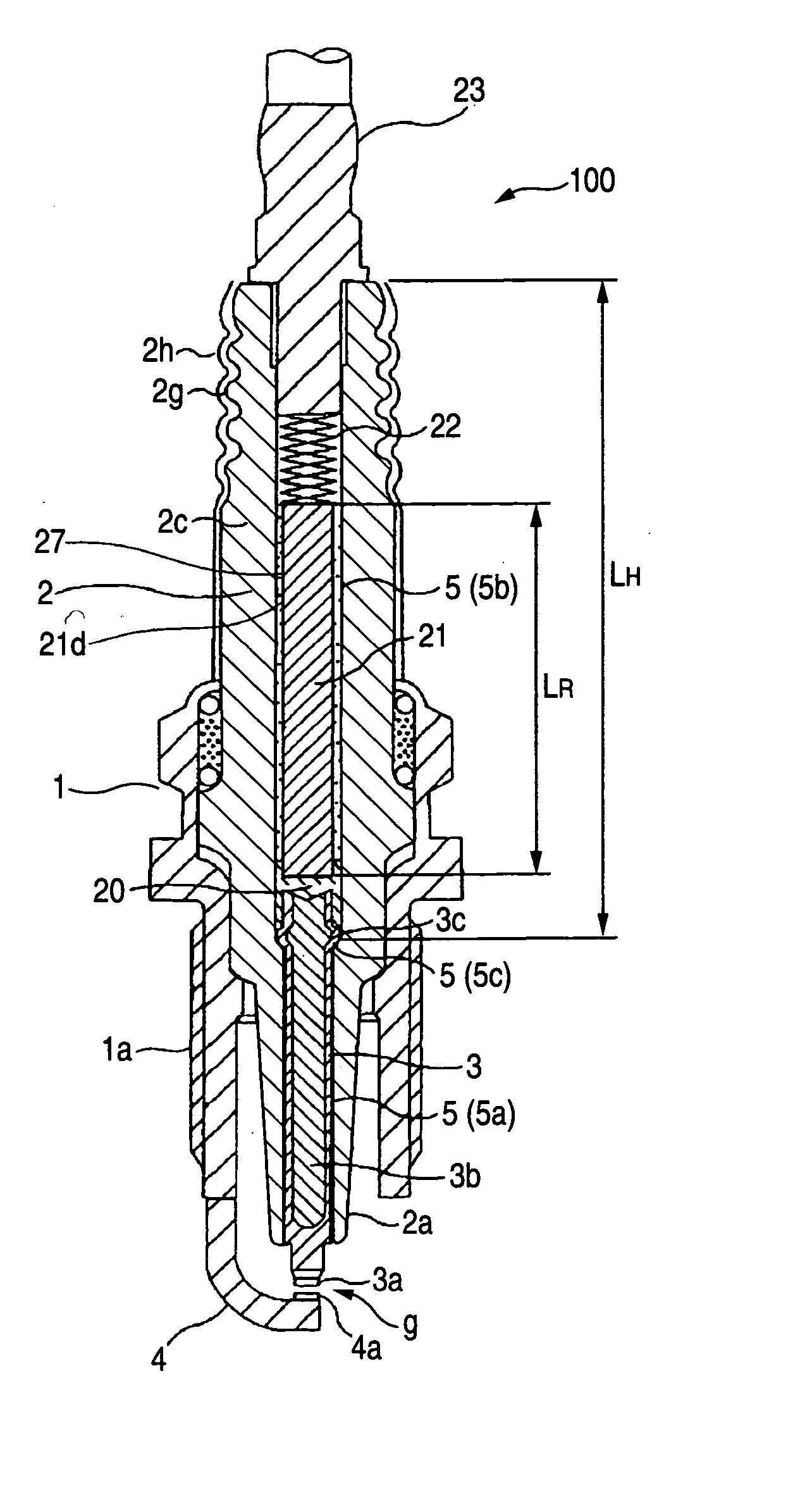
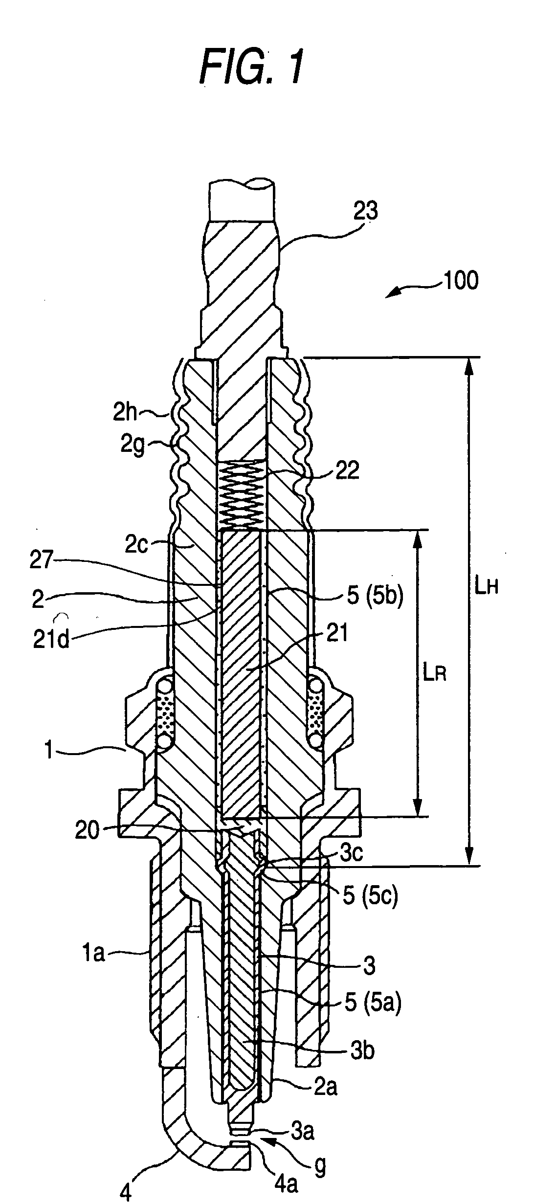
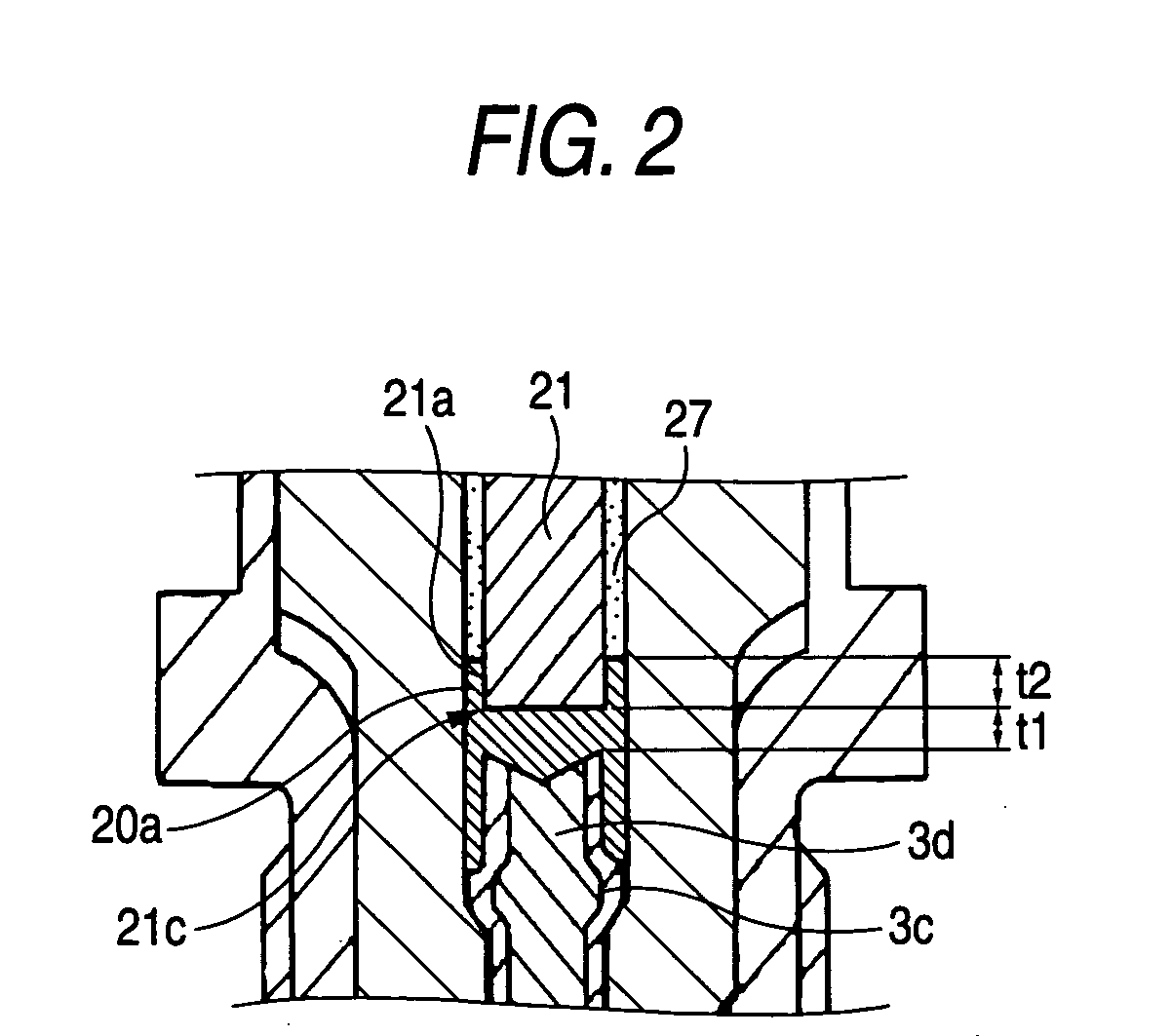
[0099] After the center electrode 3 had been inserted into the first portion 5a of the insulator 2, the conductive seal powder H was filled in the second portion 5bon the rear end side of the center electrode 3 and was preparatorily compressed by the, holding rod 30 to form the conductive seal powder layer 20a.

[0100] Next, the sintered ceramic resistor 21, composed mainly of steatite as the aggregate and tin oxide as the conductive powder and which had a length (LR) adjusted to 40% or more of the length (LH) of the second portion 5b, was inserted into the through hole 5b of the insulator 2 on the rear end side of the conductive seal powder layer 20a. After these were inserted into the heating oven, they were heated to 90°...


PUM


Abstract

A spark plug including: an insulator having a through hole extending in an axial direction, the through hole including, a first portion and a second portion provided on a rear end side of the first portion, the second portion having a larger diameter than that of the first portion; a center electrode provided in the first portion; an external terminal provided in the second portion; and a sintered ceramic resistor provided in the second portion. The sintered ceramic resistor is formed from a sintered body of a conductive ceramic, connecting the center electrode and the external terminal electrically, and having a length in an axial direction of 40% or more of a length in an axial direction of the second portion of the through hole.

Description

BACKGROUND OF THE INVENTION [0001] 1. Field of the Invention [0002] The present invention relates to a spark plug for use in an internal combustion engine and, more particularly, to a spark plug having a sintered ceramic resistor assembled therein for preventing radio wave noise. [0003] 2. Description of the Related Art [0004] A spark plug known in the related art for an internal combustion engine comprises: a cylindrical insulator having a through hole in an axial direction; a center electrode fitted in one end portion of the through hole; an external terminal fitted in the other end portion of the through hole; and a main fitting fitted on the outer circumference of the insulator. Moreover, gas tightness between the center electrode and the external terminal and the through hole of the insulator is maintained by a glass sealing method. In this method a conductive glass seal member substantially composed of a mixture of metal powder and glass powder is filled in the through hole be...

Claims


Application Information

Patent Timeline
IPC IPC(8): H01T13/20
CPCH01T13/34H01T13/41
Inventor SHIBATA, TSUTOMUTANABE, HIROYUKI
Owner NGK SPARK PLUG CO LTD
Why Eureka
Try Eureka