Charger and integrated circuit

Inactive Publication Date: 2006-04-13
RENESAS ELECTRONICS CORP
View PDF10 Cites 7 Cited by
  • Summary
  • Abstract
  • Description
  • Claims
  • Application Information

AI Technical Summary

Benefits of technology

[0011] According to the present invention, the current source supplying the second charging current is provided inside the charging integrated circuit, so the secondary battery can be charged with the second charging current as well as the first charging current supplied from the charging transistor. Consequently, heat generation can be suppressed even when the charging current increases.
[0013] According to the present invention, the two current sources are provided to simultaneously charge the secondary battery. One of the two parts and the charging control circuit are incorporated into one package, so the first charging current from the first current source is reduced a part of the total charging current, and the current source is packaged with the charging control circuit. Hence, there is no need to increase the number of components.
[0015] According to the present invention, the charging control circuit controlling the charging transistor charging the secondary battery is provided with the current source for charging the secondary battery together with the charging transistor, and thus imparted with a charging function. Hence, the circuit can charge the secondary battery together with the charging transistor to minimize the charging current flowing through the charging transistor and suppress the heat generation.

Problems solved by technology

Along with this, there is a tendency to increase the charging current for shortening a charging period.
Such a large current causes a problem that the heat generation of the charging transistor is increased.

Method used


Image

  • Charger and integrated circuit
  • Charger and integrated circuit

Examples


Embodiment Construction

[0019] The invention will be now described herein with reference to illustrative embodiments. Those skilled in the art will recognize that many alternative embodiments can be accomplished using the teachings of the present invention and that the invention is not limited to the embodiments illustrated for explanatory purposed.

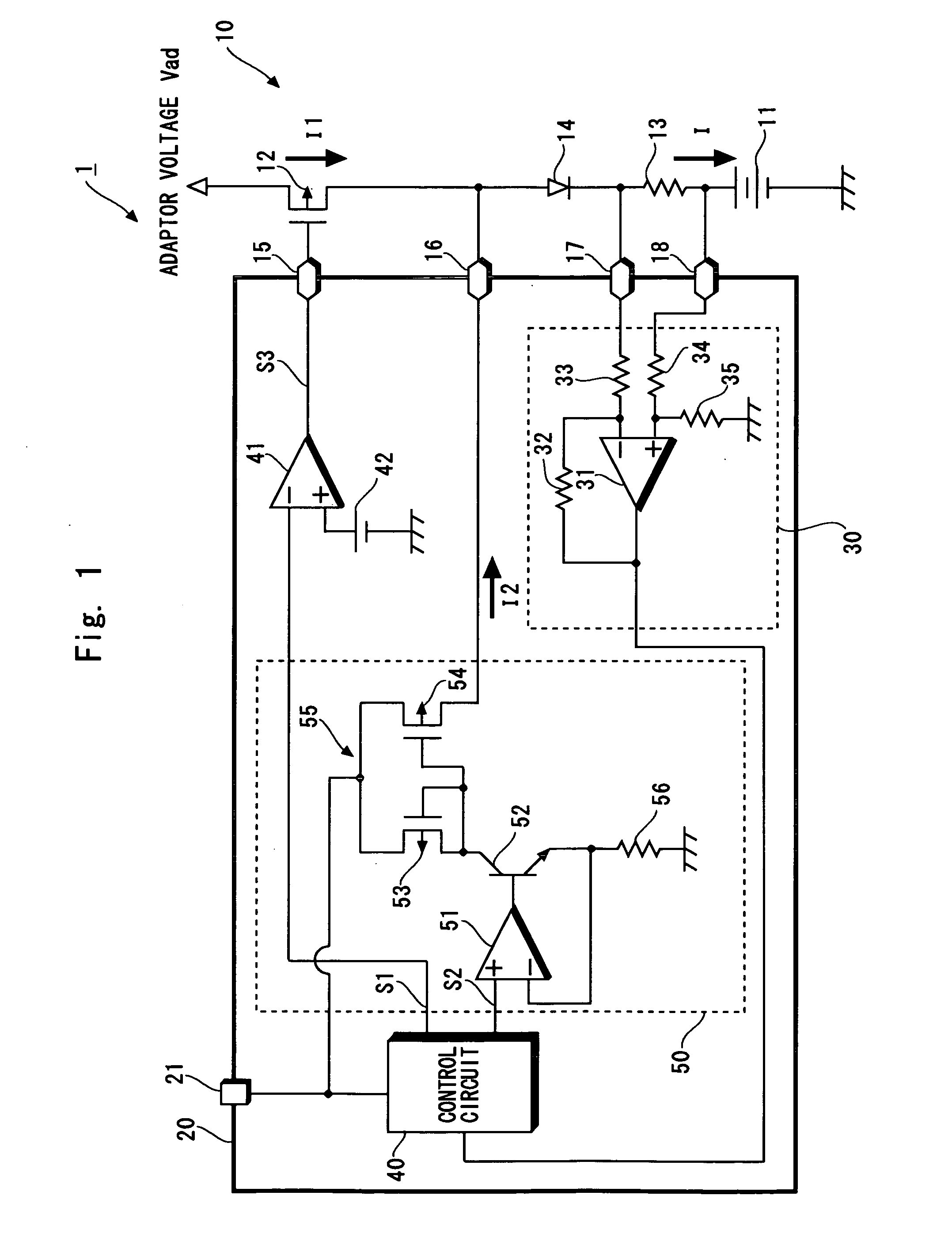
[0020] Hereinafter, an embodiment of the present invention is described in detail with reference to the accompanying drawings. This embodiment is such that the present invention is applied to a charger for charging a secondary battery used in, for example, a cellular phone. A charging integrated circuit according to this embodiment, and a charger using the same can disperse heat generated during the charging.

[0021]FIG. 1 shows a charger according to the embodiment of the present invention. A charger 1 includes a first charging current source 10 for charging a secondary battery 11, and a charging integrated circuit 20 capable of charging the secondary battery 1...


PUM


Abstract

A charger of the present invention includes a charging transistor and a charging integrated circuit. The charging transistor is series-connected with a secondary battery to supply a charging current to the secondary battery. The charging integrated circuit is incorporated into a package having a higher heat releasability than that of the charging transistor. The charging integrated circuit controls the charging transistor and besides, supplies a charging current to the secondary battery. For this purpose, the charging integrated circuit includes a current source supplying this charging current. The charging current from the current source is supplied to the secondary battery together with the charging current from the charging transistor to charge the secondary battery.

Description

BACKGROUND OF THE INVENTION [0001] 1. Field of the Invention [0002] The present invention relates to a charger for charging a secondary battery of, for example, a cellular phone, and an integrated circuit capable of controlling a charging operation for the secondary battery is charged. [0003] 2. Description of Related Art [0004] In general, a secondary battery (secondary cell) has been used as a power source of a cellular phone etc. Referring now to FIG. 2, a conventional charger for charging the cellular phone etc. is described. As shown in FIG. 2, a conventional charger 101 includes a charging current source 110, and a charging control circuit 120. The charging current source 110 supplies charging current to the secondary battery 111. The charging control circuit 120 controls the charging current source 110. The charging current source 110 is composed of a charging transistor 112, a diode 114, a detection resistor 113, and the secondary battery 111, which are connected in series. ...

Claims


Application Information

Patent Timeline
IPC IPC(8): H02J7/00
CPCH02J7/0052H02J7/00
Inventor OKAMOTO, MANABUMORI, KIYOSHI
Owner RENESAS ELECTRONICS CORP
Why Eureka
Try Eureka