Out-of-focus detection method and imaging device control method

a control method and detection method technology, applied in the field of out-of-focus detection methods, imaging devices, and control methods of imaging devices, can solve the problems of difficult for users to accurately determine whether the object image displayed on the liquid crystal monitor is in focus or out of focus, and the accuracy of the art out-of-focus detection method is relatively poor, so as to reduce processing load and improve evaluation potential

Inactive Publication Date: 2006-04-13
SEIKO EPSON CORP
View PDF15 Cites 62 Cited by
  • Summary
  • Abstract
  • Description
  • Claims
  • Application Information

AI Technical Summary

Benefits of technology

[0023] The third out-of-focus detection method computes an edge evaluation value, which represents an edge level at each of multiple evaluation positions included in an object image, from luminance information with regard to each of pixels constituting the object image, and divides the object image into multiple blocks. The third out-of-focus detection method then categorizes each block as an in-focus block or an out-of-focus block, based on edge evaluation values at respective evaluation positions included in the block, and evaluates the object image as out-of-focus or in-focus, based on rates of an in-focus area consisting of categorized in-focus blocks and of an out-of-focus area consisting of categorized out-of-focus blocks to the whole object image. The third out-of-focus detection method specifies the in-focus area and the out-of-focus area according to the edge level and evaluates the object image as out-of-focus or in-focus, based on the rates of the in-focus area and the out-of-focus area to the whole object image. This arrangement ensures adequate detection of an out-of-focus image. The method divides the object image into multiple blocks and executes the subsequent processing including specification of the in-focus area and the out-of-focus area in the units of these divisional blocks. This arrangement desirably reduces the processing load, compared with the prior art processing in the units of pixels.
[0024] In the third out-of-focus detection method, a smaller rate of the in-focus area and a greater rate of the out-of-focus area may give a higher potential for evaluating the object image as out-of-focus in the step (c). Further, the step (c) may evaluate the object image as out-of-focus or in-focus, based on relative positions of the in-focus area and the out-of-focus area to the whole object image.

Problems solved by technology

The prior art out-of-focus detect ion method, however, has relatively poor accuracy of out-of-focus detection under some conditions, for example, in the presence of significant noise in the object image or in the lower contrast in a focused area.
The prior art imaging device may take an out-of-focus image of the object, due to the poor technique of the user or the image taking environment.
The size and the performance of the liquid crystal monitor often make it difficult for the user to accurately determine whether the object image displayed on the liquid crystal monitor is in focus or out of focus.

Method used


Image

  • Out-of-focus detection method and imaging device control method
  • Out-of-focus detection method and imaging device control method
  • Out-of-focus detection method and imaging device control method

Examples


Embodiment Construction

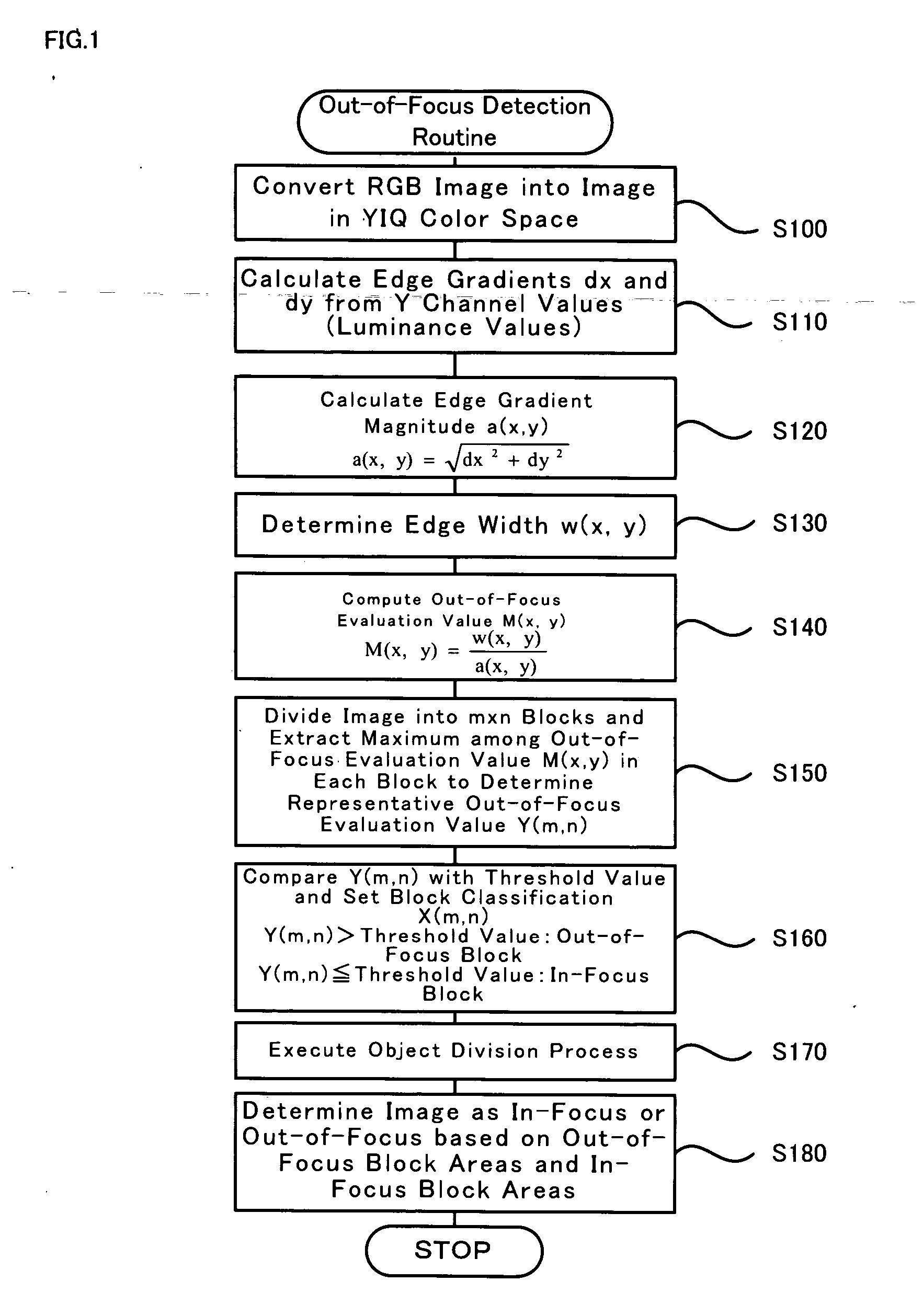
[0048] One mode of carrying out the invention is described below as a preferred embodiment. FIG. 1 is a flowchart showing a processing routine of out-of-focus detection method in one embodiment of the invention. The out-of-focus detection routine first converts an RGB image expressed in a color system of red (R), green (G), and blue (B) into a YIQ color space of three primary elements Y (luminance), I (orange-cyan), and Q (green-magenta) according to Equations (1) to (3) given below (step S100):

Y=0.299R+0.587G+0.114B  (1)

I=0.596R−0.274G+0.322B  (2)

Q=0.211R−0.523G+0.312B  (3)

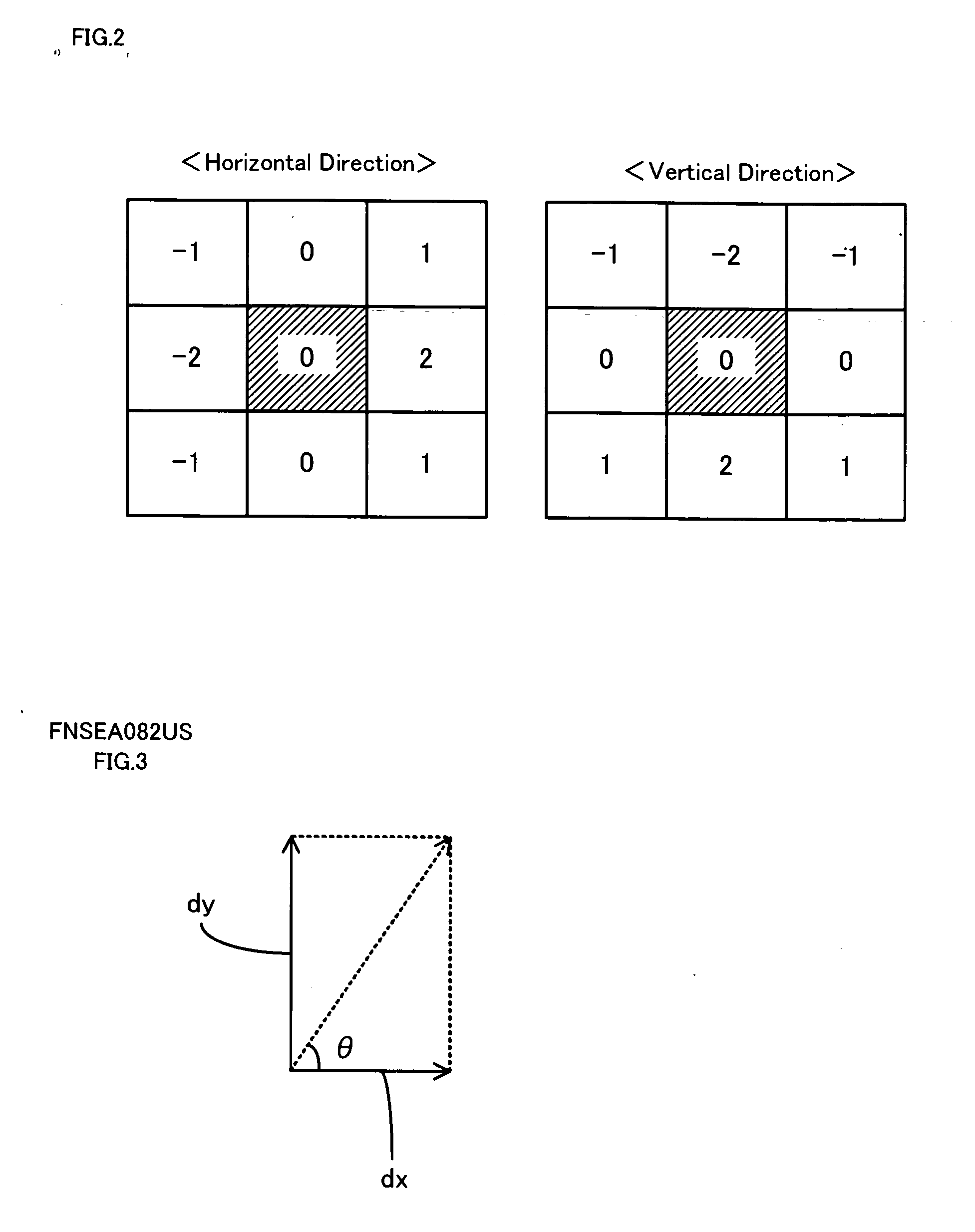
[0049] The out-of-focus detection routine then reads the Y channel values (luminance values) of the converted image in the YIQ color space and computes edge gradients dx and dy in both horizontal and vertical directions at each pixel position (x,y) (step S110). The out-of-focus detection routine calculates an edge gradient magnitude a(x,y) from the computed edge gradients dx and dy according to Equation (4) g...


PUM


Abstract

The technique of the invention calculates an edge gradient magnitude a(x,y) at each pixel position (x,y) and an edge width w(x,y) from luminance values of an object image, and computes an out-of-focus evaluation value M(x,y) at each pixel position (x,y) from the calculated edge gradient magnitude a(x,y) and edge width w(x,y). The technique then divides the object image into a preset number of blocks, determines a representative out-of-focus evaluation value Y(m,n) in each block, and compares the representative out-of-focus evaluation value Y(m,n) with a preset threshold value for block classification to categorize each block as an in-focus block or an out-of-focus block. The technique eventually determines the object image as in-focus or out-of-focus, based on the total number of blocks included in in-focus block areas, the total number of blocks included in out-of-focus block areas, and the relative positions of the in-focus block areas and the out-of-focus block areas to the whole image.

Description

BACKGROUND OF THE INVENTION [0001] 1. Field of the Invention [0002] The present invention relates to an out-of-focus detection method, an imaging device, and a control method of the imaging device. More specifically the invention pertains to an out-of-focus detection method that detects an out-of-focus image, an imaging device having the function of out-of-focus detection, and a control method of such an imaging device. [0003] 2. Description of the Prior Art [0004] One proposed out-of-focus detection method detects an edge of an object to focus a camera on the object (see, for example, Du-Ming Tsai, Hu-Jong Wang, ‘Segmenting Focused Objects in Complex Visual Images’, Pattern Recognition Letters, 1998, 19: 929-940). A known imaging device with the function of out-of-focus detection is, for example, a digital camera that displays a taken object image on a liquid crystal monitor (see, for example, Japanese Patent Laid-OpenGazette No. 2000-209467) This proposed imaging device instantly ...

Claims


Application Information

Patent Timeline
Patent Type & Authority Applications(United States)
IPC IPC(8): G06K9/40
CPCH04N5/23212H04N23/675H04N23/634H04N23/635
Inventor POON, EUNICEKANDA, MEGUMICLARKE, IAN
Owner SEIKO EPSON CORP
Why Eureka
Try Eureka