Data receiver adaptive to RSSI and a method of determining its threshold

a data receiver and threshold value technology, applied in data switching details, diversity/multi-antenna systems, transmission monitoring, etc., can solve the problems of short battery life, difficult estimation of received signals, and high rssi value of received signals, and achieve the effect of reducing convergence tim

Inactive Publication Date: 2006-04-13
LAPIS SEMICON CO LTD
View PDF3 Cites 18 Cited by
  • Summary
  • Abstract
  • Description
  • Claims
  • Application Information

AI Technical Summary

Benefits of technology

[0010] It is an object of the present invention to provide a data receiver and a method of determining its threshold value which are able to follow the turbulent variation of the environmental condition for radio wave propagation and reduce the power consumption.
[0012] In the data receiver according to the invention, the threshold value generator is responsive to the quality of the threshold value supplied from the first monitor to generate a newly generated RSSI threshold value to supply the value to the second monitor, the threshold value set in the second monitor being variable to converge, thus making it possible to reduce the convergence time of the RSSI threshold value and provide a precise threshold value of the RSSI signal
[0014] In the method of determining a threshold value according to the invention, in the noise mode, a step size, A, is added to the RSSI threshold value, and then error of the received signal is detected. Corresponding to whether or not error exists, the processing is advanced to the first step or to the first stage of optimizing the RSSI threshold value with a minute step size subtracted from the added RSSI threshold value before advancing to the first stage, error being detected again. After the detection, corresponding to whether or not the error exists, the processing is advanced to the second stage of optimizing or to the fourth step. Then, a minute step size is added to the RSSI threshold value, which is the result of operation done before the second stage, to detect error of the received signal again. By returning the processing to the first step corresponding to detected error, the RSSI threshold value is rendered variable to converge to a value optimal for the environmental condition. The method according to the invention is thus able to reduce the convergence time of the threshold value and provide a precise RSSI threshold value.
[0016] In the method of determining a threshold value according to the invention, the received signal power level in the normal mode is measured, and the noise power level is decided as the difference between the RSSI signal level (power) and the measured power level of the received signal. Then, a step size is generated which is an integral multiple of the value obtained by subtracting the RSSI threshold value in the normal mode from the noise power level. Next, the step size is added to the RSSI threshold value to detect error. Corresponding to whether or not error exists, the processing is advanced to the first step or to the changing step of RSSI threshold value, in which a value obtained by adding an integral multiple of the step size is added to the RSSI threshold value to detect error again. Corresponding to whether or not the error exists, the processing is transferred to the first or sixth step. At a result, in fast-varying noise environment, the method according to the invention is able to obtain the RSSI threshold value by a single operation without repetition, and reduce the convergence time to the optimum RSSI threshold value.

Problems solved by technology

In a highly noisy environment, however, the RSSI value of a received signal increases so high that the estimation of the received signal becomes difficult.
For example, in an intermittent receiving method disclosed in Japanese patent laid-open publication No. 2001-94505, an existing noise is erroneously determined as a carrier signal existing so that control frequently shifts itself to a continuous receiving state, therefore, power being supplied to the receiver circuit in a longer period of time.
As a result, there is a phenomenon of short battery life.
By means of this processing, transfer to the second stage of intermittent receiving becomes more difficult and thus it is possible to keep the battery life long in noisy environment.
However, the environmental condition for radio wave propagation is not always calm, so that it may be disturbed turbulently.
This turbulence includes noise deterioration and / or amelioration.
That may cause unnecessary actions to be increased for adjusting to obtain the optimum threshold value, thus increasing power consumption.

Method used


Image

  • Data receiver adaptive to RSSI and a method of determining its threshold
  • Data receiver adaptive to RSSI and a method of determining its threshold
  • Data receiver adaptive to RSSI and a method of determining its threshold

Examples


Embodiment Construction

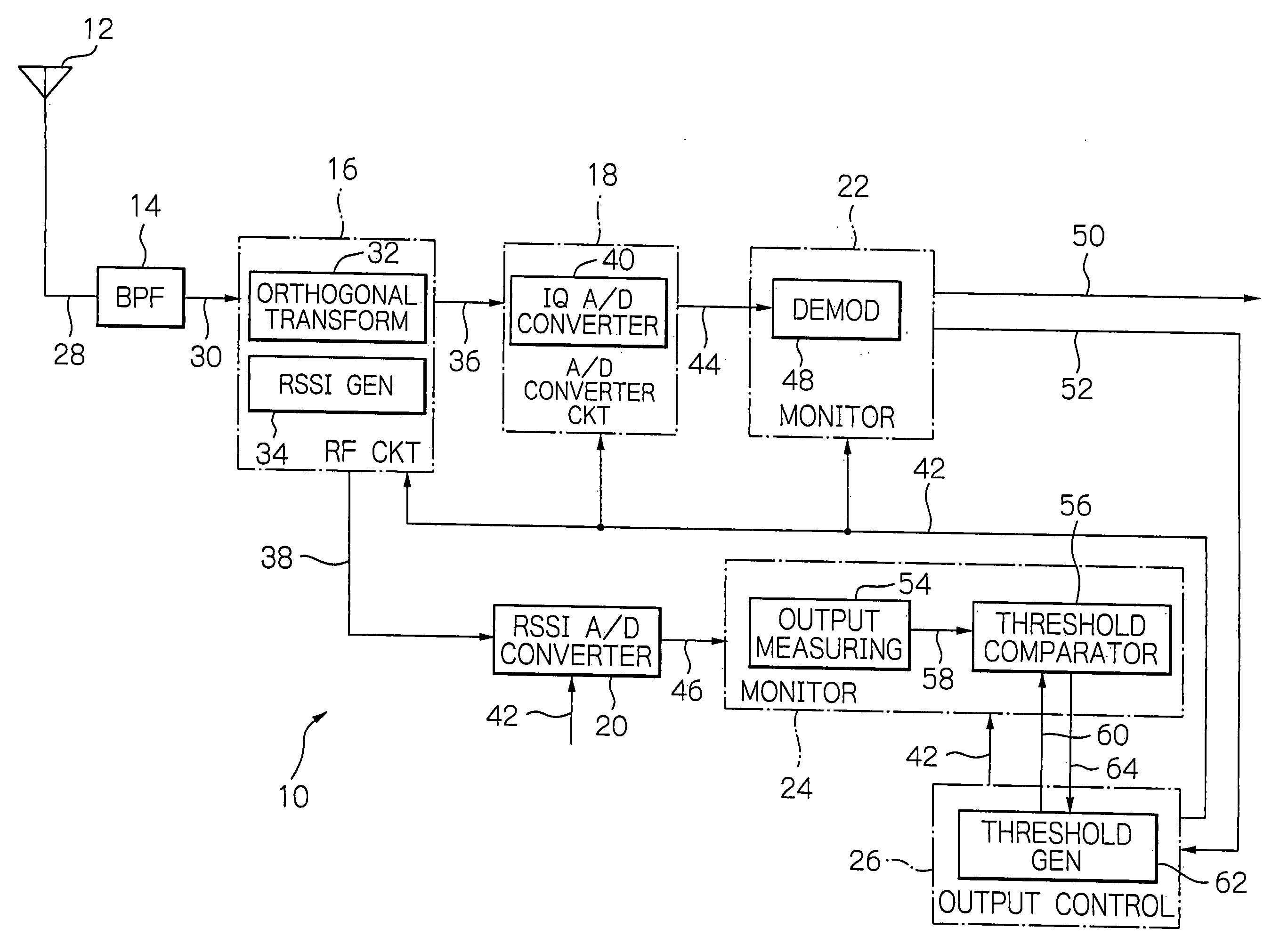
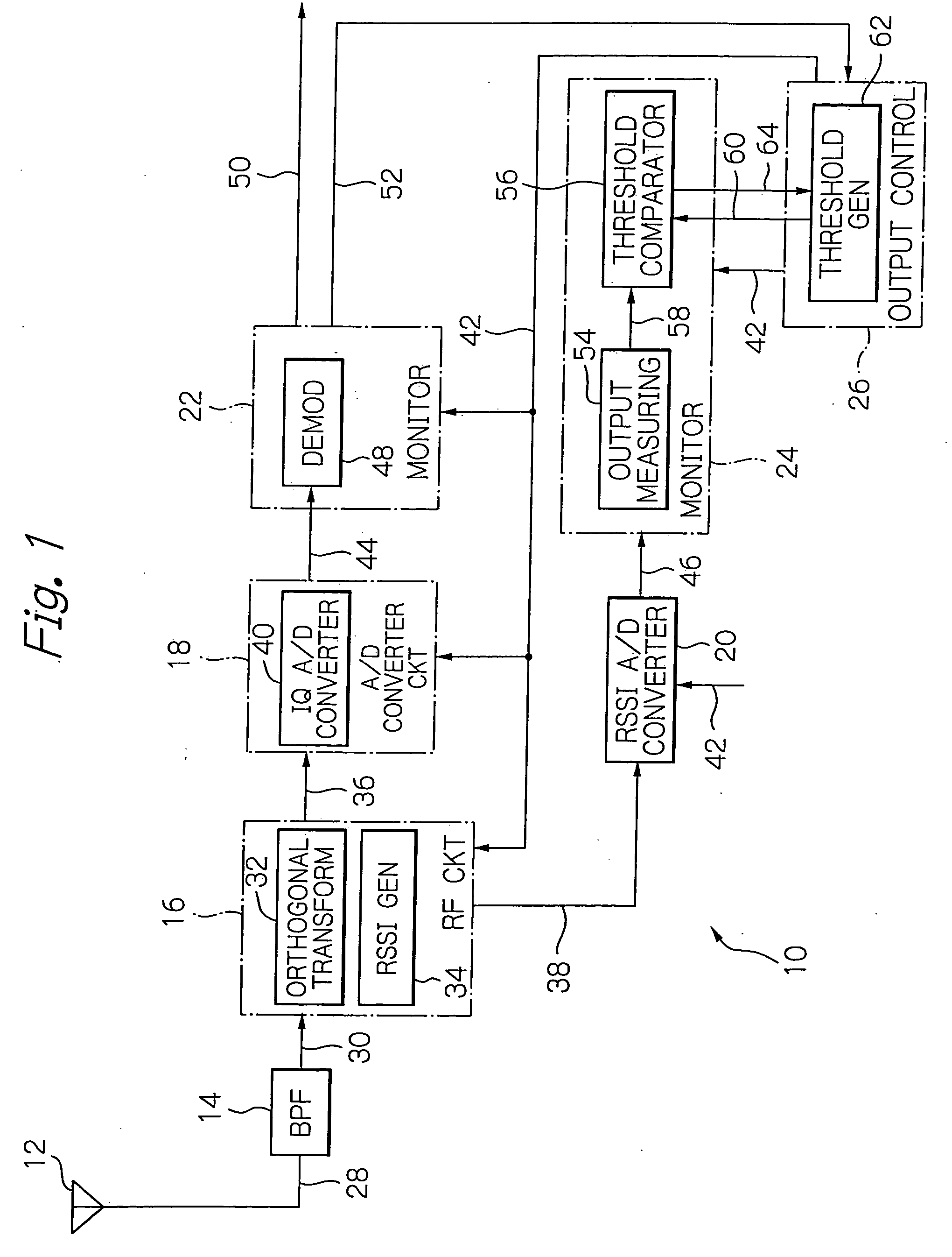
[0026] The preferred embodiments of the data receiver according to the invention will be described in detail with reference to the accompanying drawings. The illustrative embodiment is directed to a modem 10 to which a data receiver is applied according to the invention.

[0027] As shown in FIG. 1, the modem 10 comprises an antenna 12, a bandpass filter (BPF) 14, a radio frequency (RF) circuit 16, an analog-to-digital (A / D) converter circuit 18, a received signal strength indication (RSSI) analog-to-digital converter 20, monitors 22 and 24, and an output control 26, which are interconnected as illustrated. For the modem 10 in FIG. 1, since the invention is aimed mainly at its receiver facility, description will be omitted on its transmitter facility. Likewise, elements not directly relevant to understanding the invention are omitted from the figures and description. The antenna 12 provides functions to catch incoming radio waves and emit a transmitting signal received from the RF cir...


PUM


Abstract

A modem generates a new RSSI threshold value in response to a flag signal representing the quality of the threshold value indicated by the result of error detection supplied from one monitor, and supplies the generated threshold value to another monitor. The RSSI threshold value set in the other monitor is rendered variable, the modem thus being able to operate with the threshold value converging precisely in a short time.

Description

BACKGROUND OF THE INVENTION [0001] 1. Field of the Invention [0002] The present invention relates to a data receiver and a method of determining its threshold value. More specifically, the invention relates to a data receiver used in a wireless local area network (LAN) according to the standard IEEE (Institute of Electrical and Electronics Engineers) 802.11. [0003] The invention also specifically relates to a method of determining the threshold value of a data receiver in which method he threshold value based on the received signal strength indication (RSSI) is adaptively changed so as to select and set an optimum threshold value in noisy environment. [0004] 2. Description of the Background Art [0005] Conventional modems are adapted to be out of operation in order to reduce the power consumption thereof when a received signal is estimated by means of an RSSI signal. A wireless digital synchronized system disclosed in Japanese patent laid-open publication No. 2003-273796 has a config...

Claims


Application Information

Patent Timeline
Patent Type & Authority Applications(United States)
IPC IPC(8): H04B17/00H04B1/26
CPCH04B17/318H04L12/28H04L12/16
Inventor ATSUMI, TSUYOSHI
Owner LAPIS SEMICON CO LTD
Why Eureka
Try Eureka