Minimally invasive method and apparatus for placing facet screws and fusing adjacent vertebrae

a facet screw and minimally invasive technology, applied in the field of minimally invasive methods and apparatuses for placing facet screws and fusing adjacent vertebrae, can solve the problems of pseudoarthrosis, post-operative stability, traumatic time-consuming, etc., and achieve the effect of minimal invasiveness

Inactive Publication Date: 2006-04-13
THE CLEVELAND CLINIC FOUND
View PDF13 Cites 117 Cited by
  • Summary
  • Abstract
  • Description
  • Claims
  • Application Information

AI Technical Summary

Benefits of technology

[0018] In accordance with further aspects of the inventive method, the cannula is moved from its position over the lamina on the first side of the upper vertebrae and the first and second block members are released to allow relative movement. The second block member is swiveled to aim the centerline of the cannula along a fourth axis toward the facet joint on the first side previously secured with the first screw. Percutaneous access to the facet joint on the first side is obtained via the cannula and a bone graft material is placed through the cannula into the facet joint on the first side around the previously implanted first screw to assist with fusion of the upper and lower vertebrae.
[0019] An example apparatus in accordance with the present invention places translaminar screws across a facet joint between adjacent first and second vertebrae in a minimally invasive surgical procedure. The apparatus includes a first K-wire, a second K-wire, a first fixation block, a second fixation block, a support block, a first rod member, a second rod member, and a cannula. The first K-wire is inserted into the spinous process of the first vertebrae. The second K-wire is inserted into a transverse process of the second vertebrae. The first fixation block has perpendicularly extending first and second passages. The first K-wire extends into the first passage in the first fixation block. The second fixation block has perpendicularly extending first and second passages. The second K-wire extends into the first passage in the second fixation block. The support block has perpendicularly extending first and second passages. The first K-wire extends into the first passage in the support block. The first rod member extends through the second passage in the first fixation block and the second passage in the second fixation block. The second rod member further secures the first and second fixation blocks to the first and second vertebrae. The second rod member extends through the second passage in the support block. The cannula enables implantation of the translaminar screws across a facet joint between the first and second vertebrae.
[0020] An example minimally invasive apparatus in accordance with the present invention places screws across a facet joint between adjacent first and second vertebrae in a minimally invasive surgical procedure. The apparatus includes a first K-wire, a second K-wire, a first fixation block, a second fixation block, a support block, a first rod member, a support apparatus, and a cannula. The first K-wire is inserted into a spinous process of the first vertebrae. The first fixation block is removably connected to the first K-wire. The second K-wire is inserted into a transverse process of the second vertebrae. The second fixation block is removably connected to the second K-wire. The first rod member is removably connected to both of the first and second fixation blocks. The support apparatus further secures the first and second K-wires to the first and second vertebrae. The cannula enables implanting of the screws across the facet joint between the first and second vertebrae.

Problems solved by technology

These and other known spinal fixation and / or fusion procedures can be quite invasive, traumatic, and time consuming.
Further, problems with post-operative stability and pseudoarthrosis are often associated with many of these procedures.

Method used


Image

  • Minimally invasive method and apparatus for placing facet screws and fusing adjacent vertebrae
  • Minimally invasive method and apparatus for placing facet screws and fusing adjacent vertebrae
  • Minimally invasive method and apparatus for placing facet screws and fusing adjacent vertebrae

Examples


Embodiment Construction

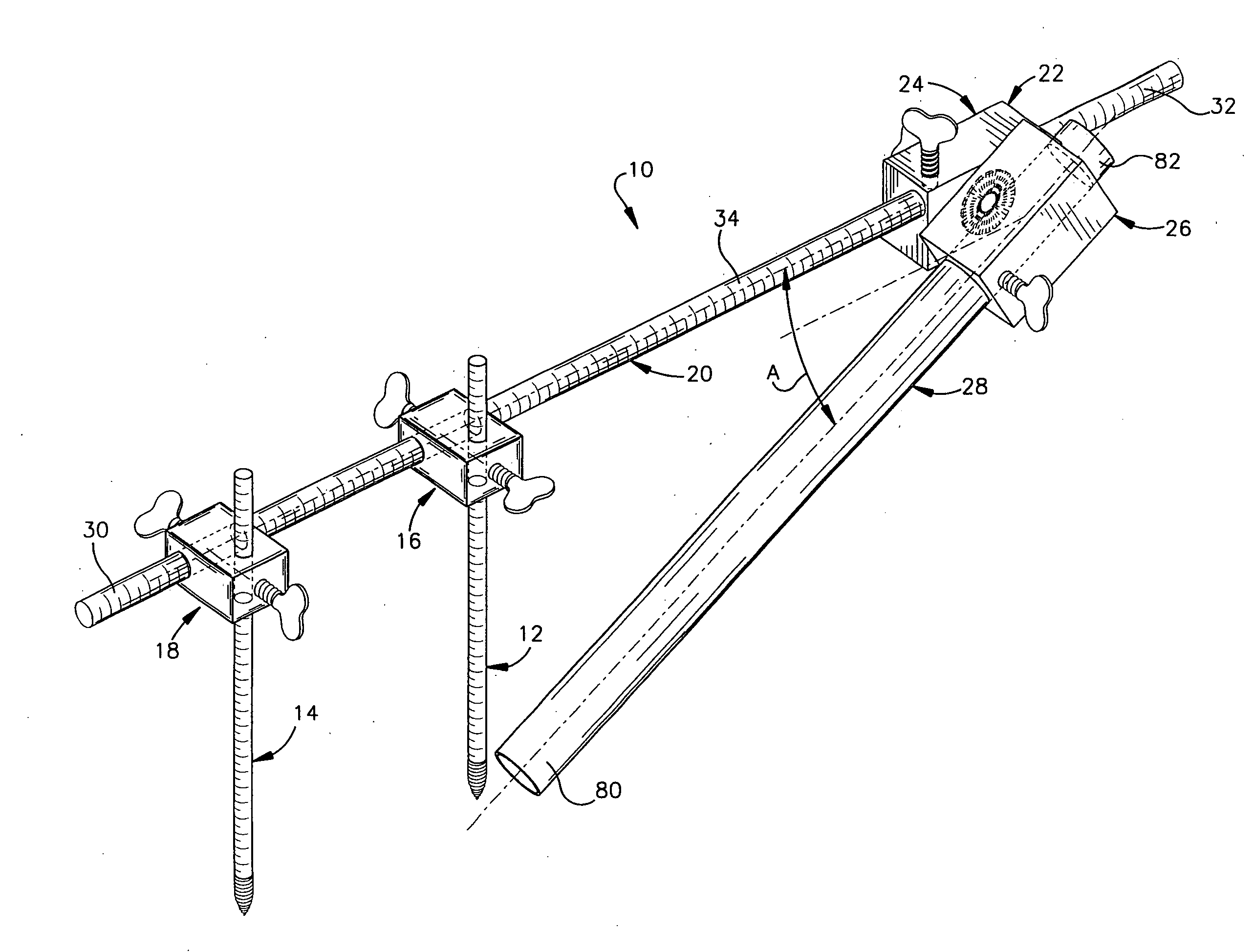
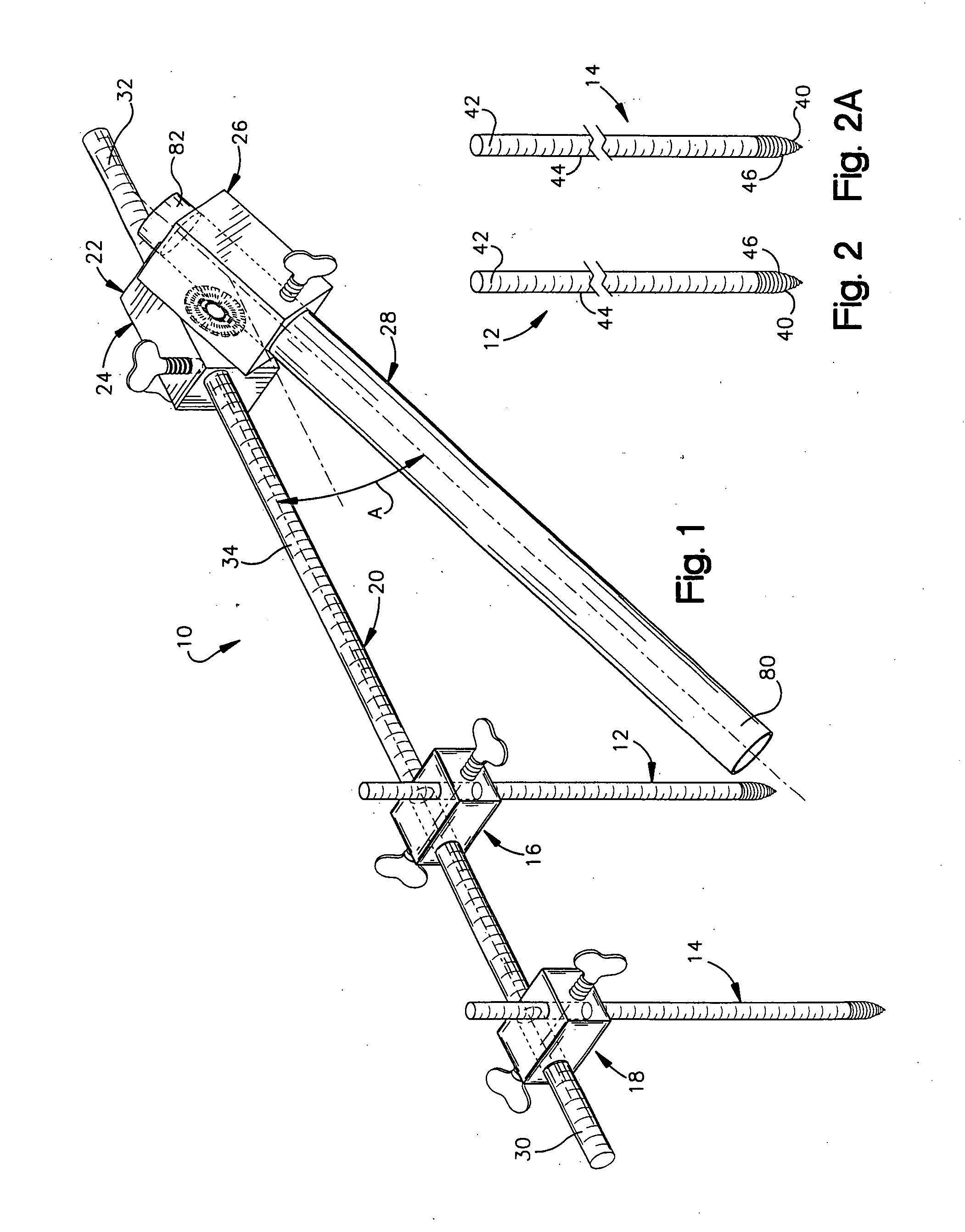
[0056] The present invention relates to a minimally invasive method and apparatus for placing facet screws and fusing adjacent vertebrae. As representative of the present invention, FIG. 1 illustrates an apparatus 10 comprising first and second Kirschner wires 12 and 14 (commonly referred to as “K-wires”), first and second fixation blocks 16 and 18, a rod member 20, a swivel block assembly 22 comprising first and second block members 24 and 26, and a cannula 28.

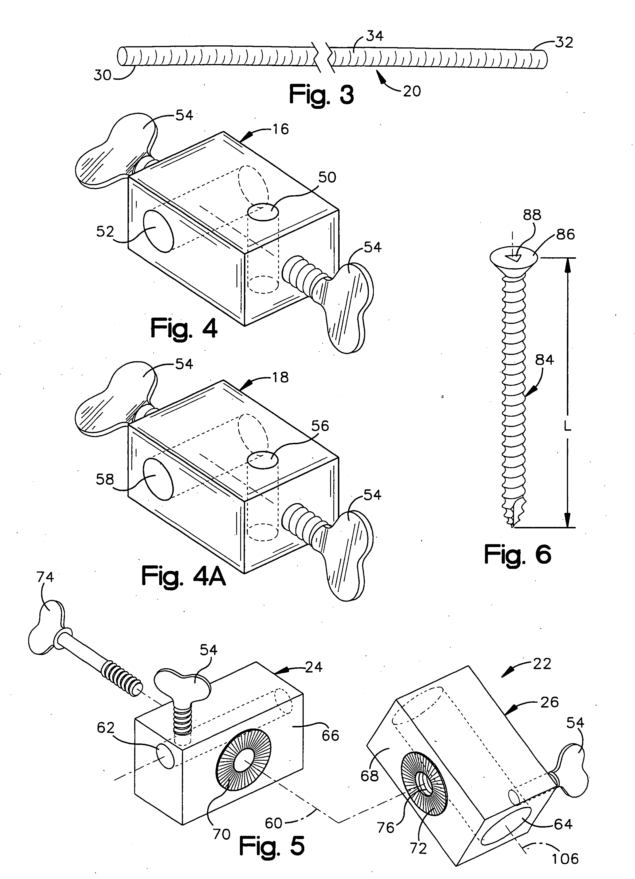
[0057] As may be seen in FIG. 3, the rod member 20 is a cylindrical component that may be hollow or solid and is made from any suitable metal or plastic. The rod member 20 has oppositely disposed first and second ends 30 and 32 and an outer diameter of 4 to 7 mm. The rod member 20 includes an outer surface 34 with graduations for measuring axial distances along its length. It is contemplated that other means for measuring axial length along the rod member 20 could also be used.

[0058] The first and second K-wires 12 and 14 (...


PUM


Abstract

An example apparatus places translaminar screws across a facet joint between adjacent first and second vertebrae in a minimally invasive surgical procedure. The apparatus includes a first K-wire, a second K-wire, a first fixation block, a second fixation block, a support block, a first rod member, a second rod member, and a cannula. The first K-wire is inserted into the spinous process of the first vertebrae. The second K-wire is inserted into a transverse process of the second vertebrae. The first fixation block has perpendicularly extending first and second passages. The first K-wire extends into the first passage in the first fixation block. The second fixation block has perpendicularly extending first and second passages. The second K-wire extends into the first passage in the second fixation block. The support block has perpendicularly extending first and second passages. The first K-wire extends into the first passage in the support block. The first rod member extends through the second passage in the first fixation block and the second passage in the second fixation block. The second rod member further secures the first and second fixation blocks to the first and second vertebrae. The second rod member extends through the second passage in the support block. The cannula enables implantation of the translaminar screws across a facet joint between the first and second vertebrae.

Description

RELATED APPLICATION [0001] This application is a continuation-in-part of a co-pending U.S. patent application Ser. No. 10 / 952,650, entitled “MINIMALLY INVASIVE METHOD AND APPARATUS FOR PLACING FACET SCREWS AND FUSING ADJACENT VERTEBRAE”, filed Sep. 24, 2004. The subject matter of the aforementioned co-pending application is incorporated herein by reference.TECHNICAL FIELD [0002] The present invention relates to a minimally invasive method and apparatus for placing facet screws and fusing adjacent vertebrae. BACKGROUND OF THE INVENTION [0003] Over 200,000 spinal fixation and spinal fusion procedures are performed annually to correct various congenital and degenerative spinal disorders in humans. Many of these corrective surgical procedures are performed in the lumbar and lumbosacral regions of the spine where traumatic and age-related disc degeneration is common. One such procedure involves the implantation of spinal fixation instrumentation, including plates and rods, using pedicle ...

Claims


Application Information

Patent Timeline
Patent Type & Authority Applications(United States)
IPC IPC(8): A61F2/34
CPCA61B17/171A61B17/1757A61B17/7064A61B2019/461A61B2019/462A61B2090/061A61B2090/062
Inventor LIEBERMAN, ISADOR H.
Owner THE CLEVELAND CLINIC FOUND
Why Eureka
Try Eureka