
Numerical control apparatus

Active Publication Date: 2006-04-13
FANUC LTD
View PDF4 Cites 8 Cited by
  • Summary
  • Abstract
  • Description
  • Claims
  • Application Information

AI Technical Summary

Benefits of technology

[0017] Even if a plurality of detection signals are continuously inputted from the tool cutting edge detection means, the detection signal determining means determines only a first inputted detection signal from among the detection signals as effective, and determines detection signals which are inputted thereafter as invalid and eliminates the erroneous detection.
[0027] In the determination of (1), a signal which is detected until a preset time is elapsed after a first signal at the instant when the tool comes into contact with the touch sensor is received is disenabled as erroneous detection. With this, even if a plurality of signals are inputted from the touch sensor, only the first signal at the instant when the tool comes into contact with the touch sensor is received as effective, and even if the touch sensor reacts a plurality of times, erroneous detection can be eliminated and precise detection can be carried out.
[0031] According to the numerical control apparatus of the present invention, even if the touch sensor reacts a plurality of times, the erroneous detection can be eliminated and precise detection can be carried out.
[0032] Further, erroneous detection caused by the erroneous contact can be eliminated, and precise detection can be carried out.

Problems solved by technology

The numerical control apparatus executes a work program on the precondition that the cutting edge of the tool is on the reference position, but if the work program is executed while leaving the error between the cutting edge position and the reference position as it is, the machining precision is deteriorated.
When the position error is great, the tool and the machine tool interfere with each other, and a problem may be caused in the machining operation itself.
Therefore, a control apparatus is determined by a detection signal which is inputted lastly, and there is a problem that a precise tool compensation amount can not be obtained in some cases.
When the tool comes into contact with wrong touch sensor or cutter abutting surface, the detection signal is an erroneous detection signal, and if a tool compensation amount is calculated based on such erroneous detection signal, there is a problem that a precise tool compensation amount can not be obtained.

Method used


Image

  • Numerical control apparatus
  • Numerical control apparatus
  • Numerical control apparatus

Examples


Embodiment Construction

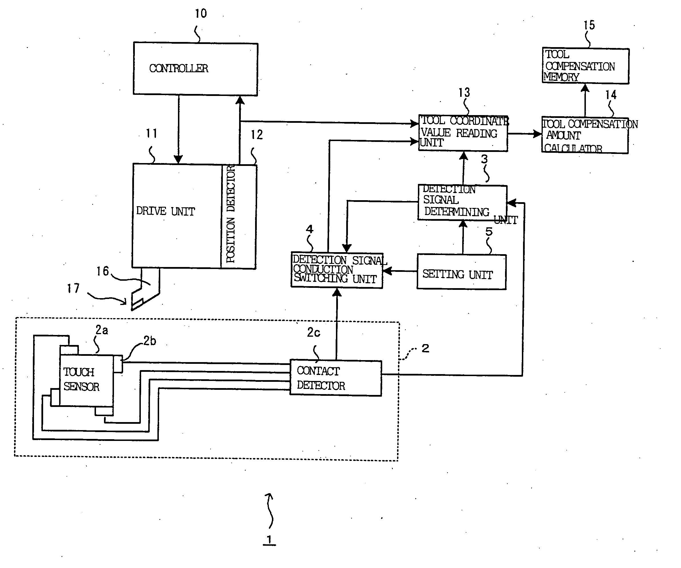
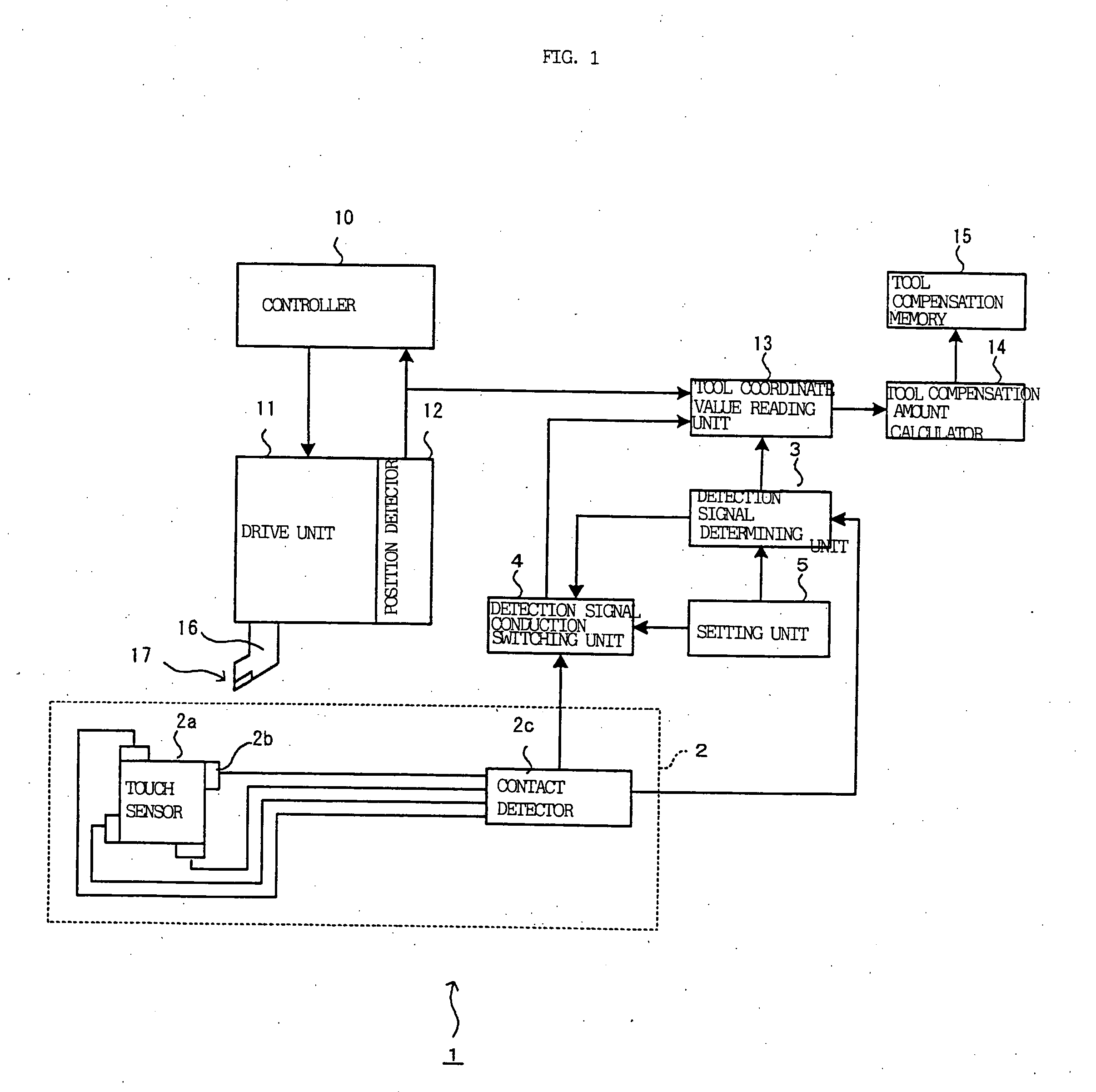
[0040] One example of a structure of a numerical control apparatus according to the present invention will be explained with reference to the block diagram of FIG. 1.

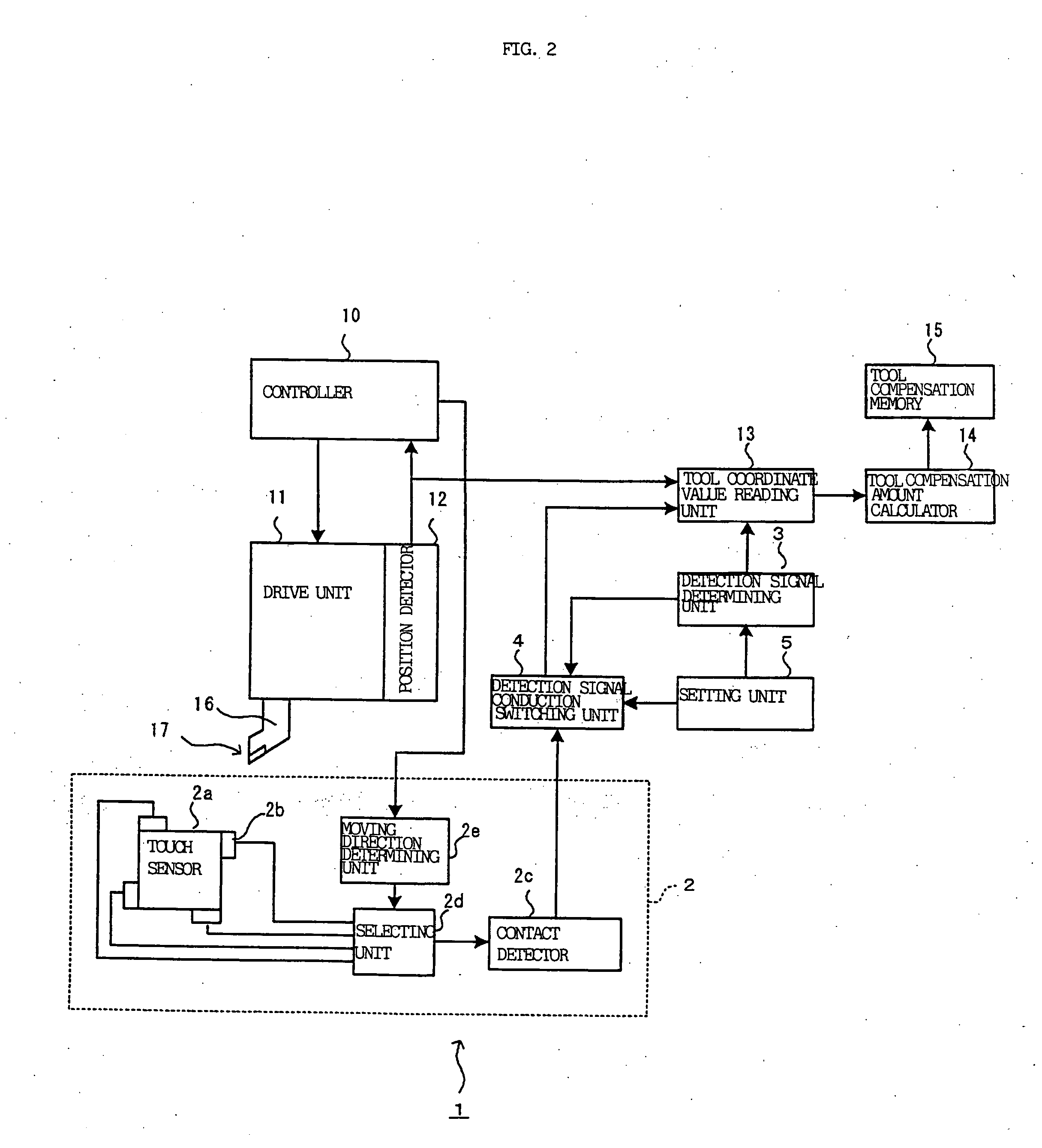
[0041] In FIG. 1, as a mechanism for driving a tool 16, a numerical control apparatus 1 comprises a controller 10 for positioning a workpiece or a tool on a position set by a work program, a drive unit 11 for controlling position, speed and the like of the tool 16 and the like under control of the controller 10, and a position detector 12 for detecting a position and the like of a drive shaft driven by the drive unit 11. A tool cutting edge 17 is mounted on a tip end of the tool 16, and the tool cutting edge 17 carries out machining of the workpiece (not shown).

[0042] As a mechanism for correcting the tool position, the numerical control apparatus 1 comprises a tool cutting edge detector 2 for detecting a position of the tool cutting edge, the tool coordinate value reading unit 13 for reading a tool compensation value...


PUM


Abstract

A numerical control apparatus having tool cutting edge detecting unit for detecting a cutting edge position of a tool mounted on a tool rest, comprises detection signal determining unit for determining, as effective, only a detection signal that is first inputted from among a plurality of detection signals which are continuously inputted from the tool cutting edge detecting unit. A signal which is detected until a preset time is elapsed after a first signal is received when the tool comes into contact with the touch sensor, and / or until the tool moves a predetermined distance, is determined as erroneous detection by the detection signal determining unit, and the signal is disenabled.

Description

BACKGROUND OF THE INVENTION [0001] 1. Field of the Invention [0002] The present invention relates to a numerical control apparatus capable of bringing a tool cutting edge of a tool mounted on a tool rest into contact with a cutting edge abutting surface of a touch sensor to detect the tool cutting edge, and setting a tool compensation amount from a cutting edge position when the tool cutting edge is detected. [0003] 2. Description of the Related Art [0004] In a machining processing of a workpiece using a numerical control apparatus, a cutting edge position of a tool mounted on a tool rest is different in some cases from a reference position set in advance as a result of tool exchanges or the like. The numerical control apparatus executes a work program on the precondition that the cutting edge of the tool is on the reference position, but if the work program is executed while leaving the error between the cutting edge position and the reference position as it is, the machining preci...

Claims


Application Information

Patent Timeline
IPC IPC(8): G06F19/00G05B19/406
CPCG05B19/4015G05B2219/37407Y10T483/138G05B2219/50139G05B2219/50135
Inventor ENDO, TAKAHIKONAGANO, KATSUNORI
Owner FANUC LTD
Learn More