Power/ground wire routing correction and optimization

Active Publication Date: 2006-04-13
SIEMENS PROD LIFECYCLE MANAGEMENT SOFTWARE INC
View PDF8 Cites 85 Cited by
  • Summary
  • Abstract
  • Description
  • Claims
  • Application Information

AI Technical Summary

Benefits of technology

[0011] Various examples of the invention provide a tool that a designer may employ to more efficiently route PG wires in a layout design of an integrated circuit. More particularly, various examples of the invention provide a PG wire routing optimization tool that analyzes a routing of PG wires for unacceptable IR-drops or electromigration problems. If one or more problems are discovered, the PG wire routing optimization tool determines design constraints for the wires that will correct the identi

Problems solved by technology

Microdevices, such as microcircuits formed on a substrate, continue to become more and more complex.
A conventional integrated circuit may contain several million transistors, making these devices very difficult to design and fabricate.
Moreover, the layout of elements in a microcircuit design typically is not a linear process.
In particular, the floor plan usually will include those wire structures that will take up a large amoun

Method used


Image

  • Power/ground wire routing correction and optimization
  • Power/ground wire routing correction and optimization
  • Power/ground wire routing correction and optimization

Examples


Embodiment Construction

Overview

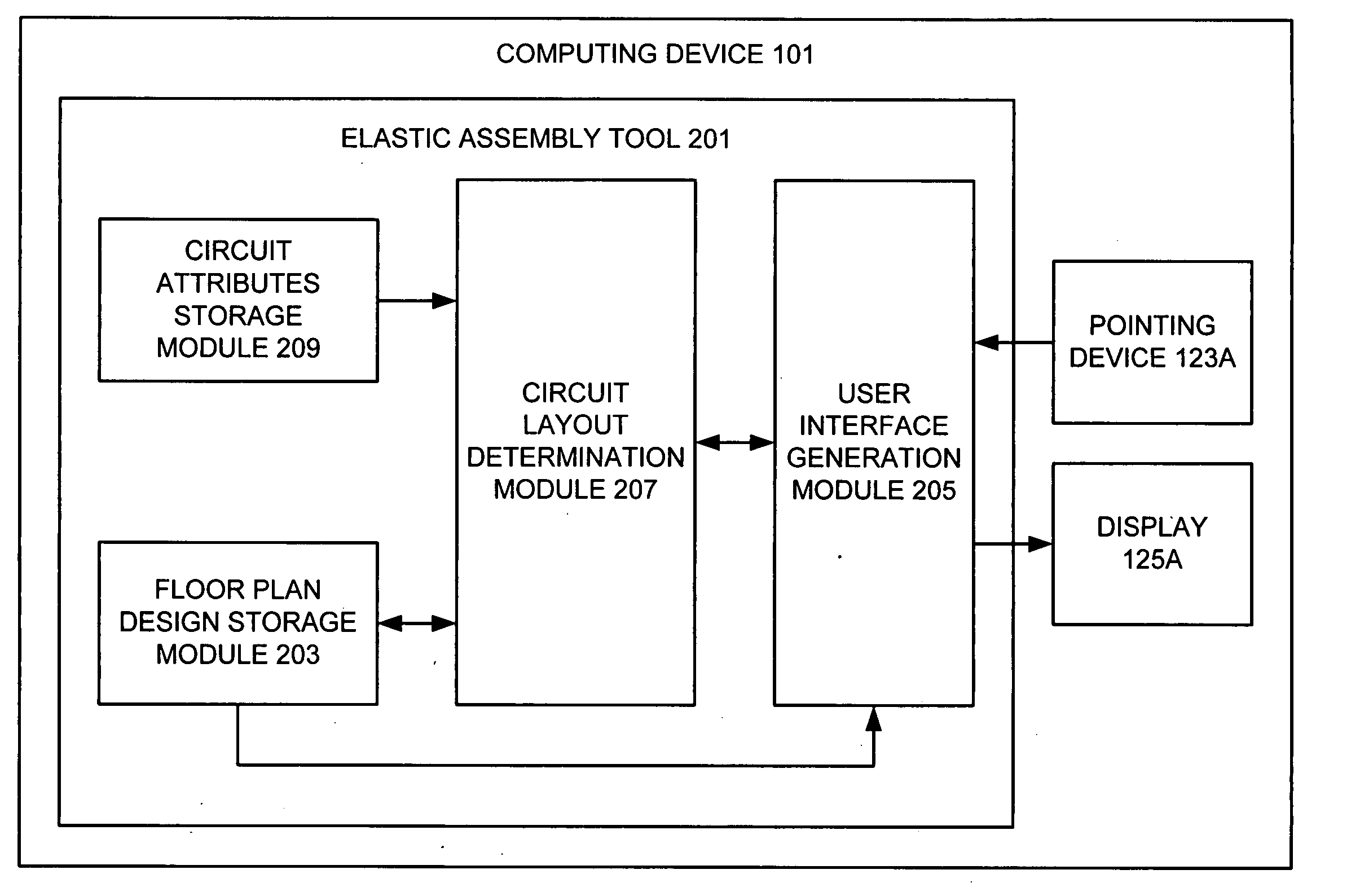
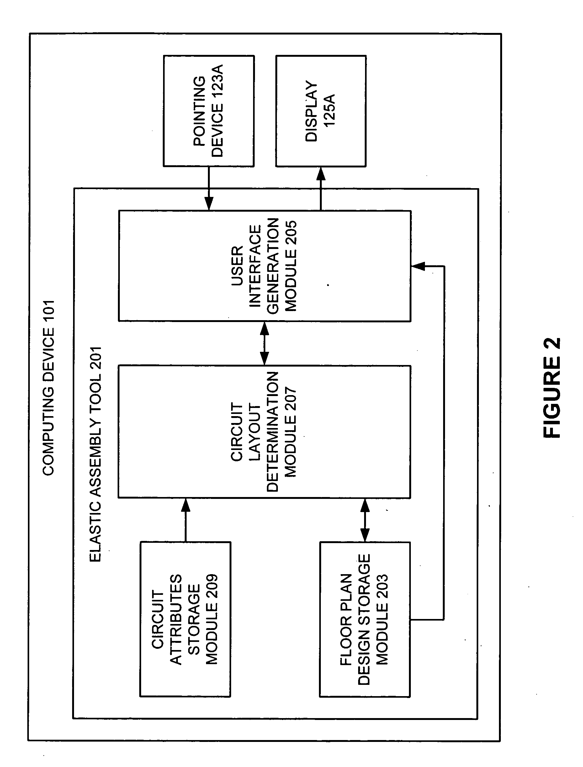
[0026] As will be discussed in more detail below, various implementations of the invention relate to a PG wire routing optimization tool that a designer may employ to more efficiently route PG wires in a layout design of an integrated circuit. With some examples of the invention, the PG wire routing optimization tool analyzes the routing of PG wires in an integrated circuit layout design for unacceptable IR-drops or electromigration problems. If one or more specified problems are discovered, the PG wire routing optimization tool determines new design constraints for the wires that will correct the identified problems. The PG wire routing optimization tool will then invoke the operation of a placement and routing tool to implement these corrective design constraints in the floor plan design. With still other examples of the invention, the PG wire routing optimization tool will alternately or additionally determine new design constraints for the wiring that will minimize the...


PUM


Abstract

A PG wire routing optimization tool for more efficiently routing PG wires in a layout design of an integrated circuit. The PG wire routing optimization tool analyzes a routing of the wires of a power and ground network for unacceptable IR-drops or electromigration problems. If one or more problems are discovered, the PG wire routing optimization tool determines design constraints for the wires that will correct the identified problems. It then initiates a floor planning tool to implement these corrective design constraints in the floor plan design. The PG wire routing optimization tool may alternately or additionally determine design constraints that will minimize the area of the wiring but will avoid creating new IR-drop or electromigration problems. It will then initiate a floor planning tool to implement these optimizing design constraints in the floor plan design.

Description

RELATED APPLICATIONS [0001] This application is a continuation-in-part application of U.S. patent application Ser. No. 10 / 979,868, entitled “Elastic Assembly Floor Plan Design Tool,” filed on Nov. 1, 2004 and naming Chih-Liang Cheng et al. as inventors, which in turn is a continuation-in-part application of U.S. Provisional Patent Application No. 60 / 517,358, entitled “Elastic Assembly Tool”, filed on Nov. 2, 2003, and naming Chih-Liang Cheng et al. as inventors, both of which applications are incorporated entirely herein by reference. This application also is a continuation-in-part application of U.S. Provisional Patent Application No. 60 / 612,877, entitled “Chip Level Power / Ground Network Optimization Methodology,” filed on Sep. 24, 2004, and naming Ta-Cheng Lin et al. as inventors, which application also is incorporated entirely herein by reference.FIELD OF THE INVENTION [0002] The present invention relates to the design of microdevices. Various aspects of the present invention are...

Claims


Application Information

Patent Timeline
IPC IPC(8): G06F17/50G06F9/455
CPCG06F17/5077G06F30/394
Inventor LIN, TA-CHENG
Owner SIEMENS PROD LIFECYCLE MANAGEMENT SOFTWARE INC
Why Eureka
Try Eureka