
Resilient routing systems and methods

Active Publication Date: 2007-03-29
RESILIENS
View PDF7 Cites 44 Cited by
  • Summary
  • Abstract
  • Description
  • Claims
  • Application Information

AI Technical Summary

Benefits of technology

[0018] In any given default configuration, there may be a number of nodes which are safe. A safe node can be the source of data, or can receive data as the final hop in the transmission over the network, but cannot forward received data to another node in the network. A simple way of doing this is to eliminate all but one link to the safe node. However, in accordance with another aspect of the invention, the method may involve retaining a plurality of links to a safe node, but each of these links will be given a high weighting—so that in calculating a route for data, none of these links would be used unless absolutely necessary, i.e. unless the safe node is the final destination in the network for the data. This allows for greater versatility in routing the data than by providing just a single active link to the safe node.
[0033] The invention contains a forwarding process that takes advantage of the backup configurations to provide fast recovery from a component failure.
[0037] The new configuration may be implemented only for links and routers which are downstream of any router which neighbours the failed link or node. The error detected could be notified back to the source so that all routers are changed to the new configuration. This could be done when the error is detected by the node neighbouring the failed node or link, or after the detecting node has already forwarded the data in accordance with the new configuration. Implementing an appropriate new configuration across the network could result in more efficient routing than simple starting from the detecting node.
[0038] A new configuration may apply to all data but preferably is implemented only for data which would otherwise be routed over the failed link or router. To simplify matters and increase speed, a new configuration may remain in place and be applicable to all relevant data, until such time as a command is received to revert to the default configuration—for example after a network administrator has dealt with the failed link or router.
[0051] MRC helps improve network availability through suppression of the re-convergence process. Delaying this process is useful to address transient failures, and pays off under many scenarios. Suppression of the reconvergence process is further actualized by the evidence that a large proportion of network failures is short-lived, often lasting less than a minute.

Problems solved by technology

A disruption of a link in central parts of a network has the potential to affect hundreds of thousands of phone conversations or TCP connections, with obvious adverse effects.
This network-wide IP re-convergence is a time consuming process, and a link or node failure is typically followed by a period of routing instability.
During this period, packets may be dropped due to invalid routes.
Much effort has been devoted to optimizing the different steps of the convergence of IP routing, i.e., detection, dissemination of information and shortest path calculation, but the convergence time is still too large for applications with real time demands.
A key problem is that since most network failures are short lived (A. Markopoulou, G. Iannaccone, S. Bhattacharyya, C.-N.
Chuah, and C. Diot, “Characterization of failures in an IP backbone network,” in Proceedings of INFOCOM2004, March 2004) too rapid triggering of the reconvergence process can cause route flapping and increased network instability.
Such an arrangement has advantages over previous systems, but in practice there may be delays in switching to an alternative layer when there is a fault in a node or a link, and there are some limitations as to the versatility of the system.

Method used


Image

  • Resilient routing systems and methods
  • Resilient routing systems and methods
  • Resilient routing systems and methods

Examples


Embodiment Construction

[0058] Some embodiments of the invention will now be described by way of example and with reference to the accompanying drawings, in which:

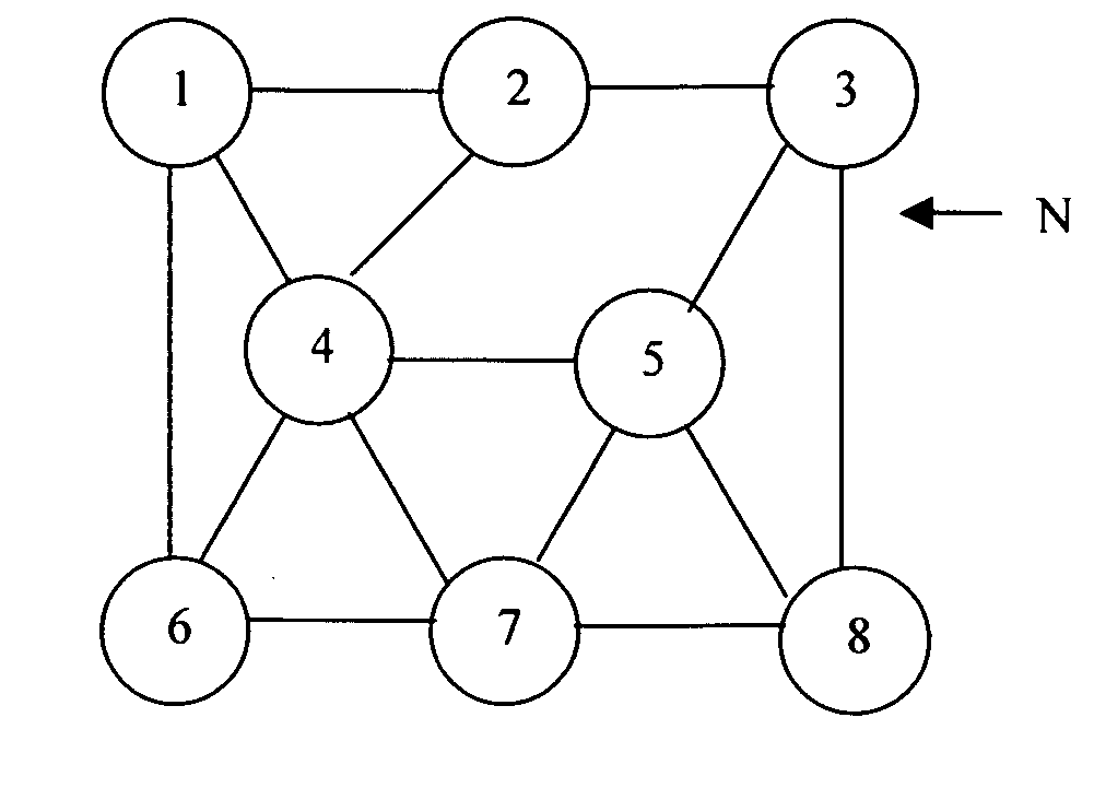
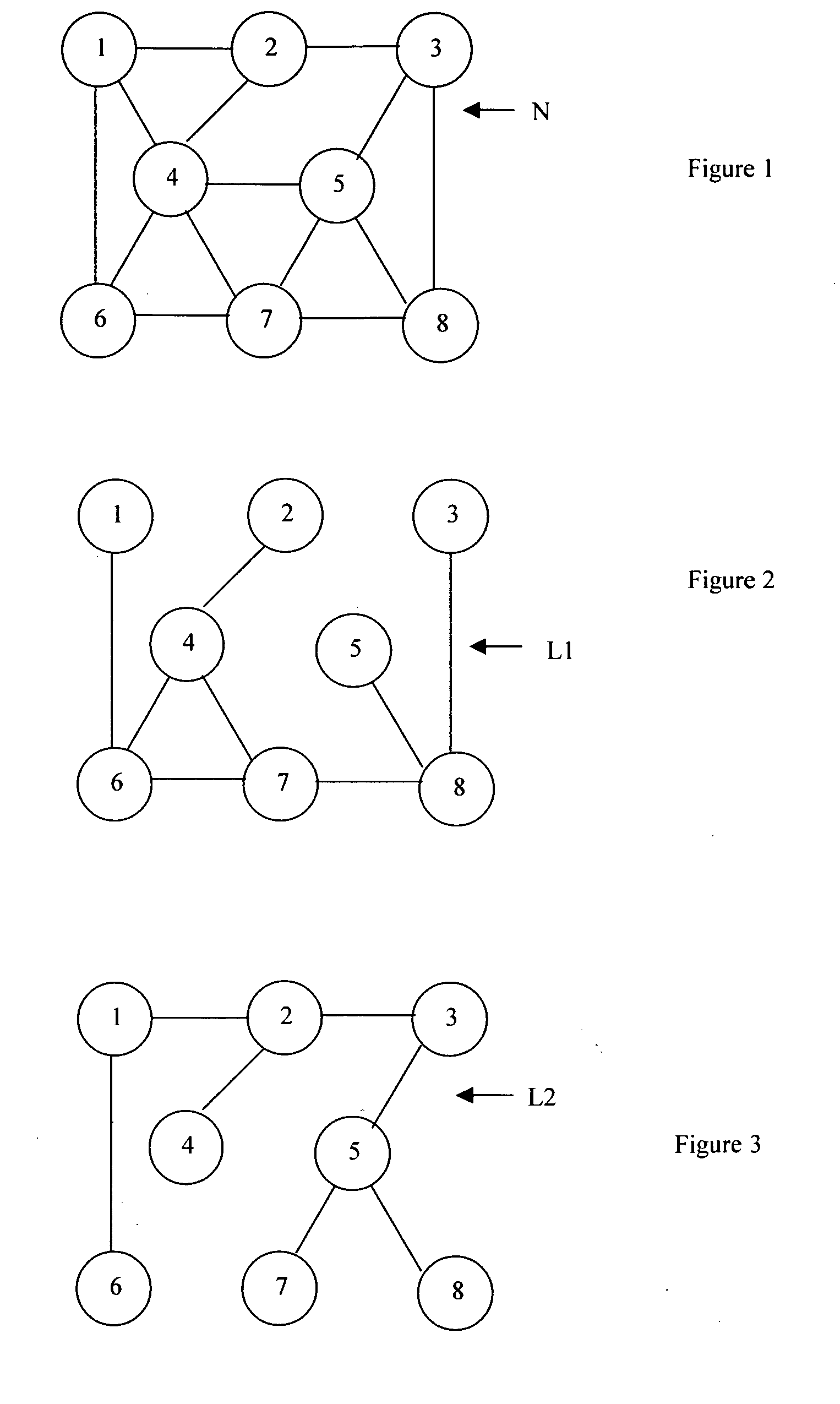
[0059]FIG. 1 is a basic network topology;

[0060]FIG. 2 is a first backup layer;

[0061]FIG. 3 is a second backup layer;

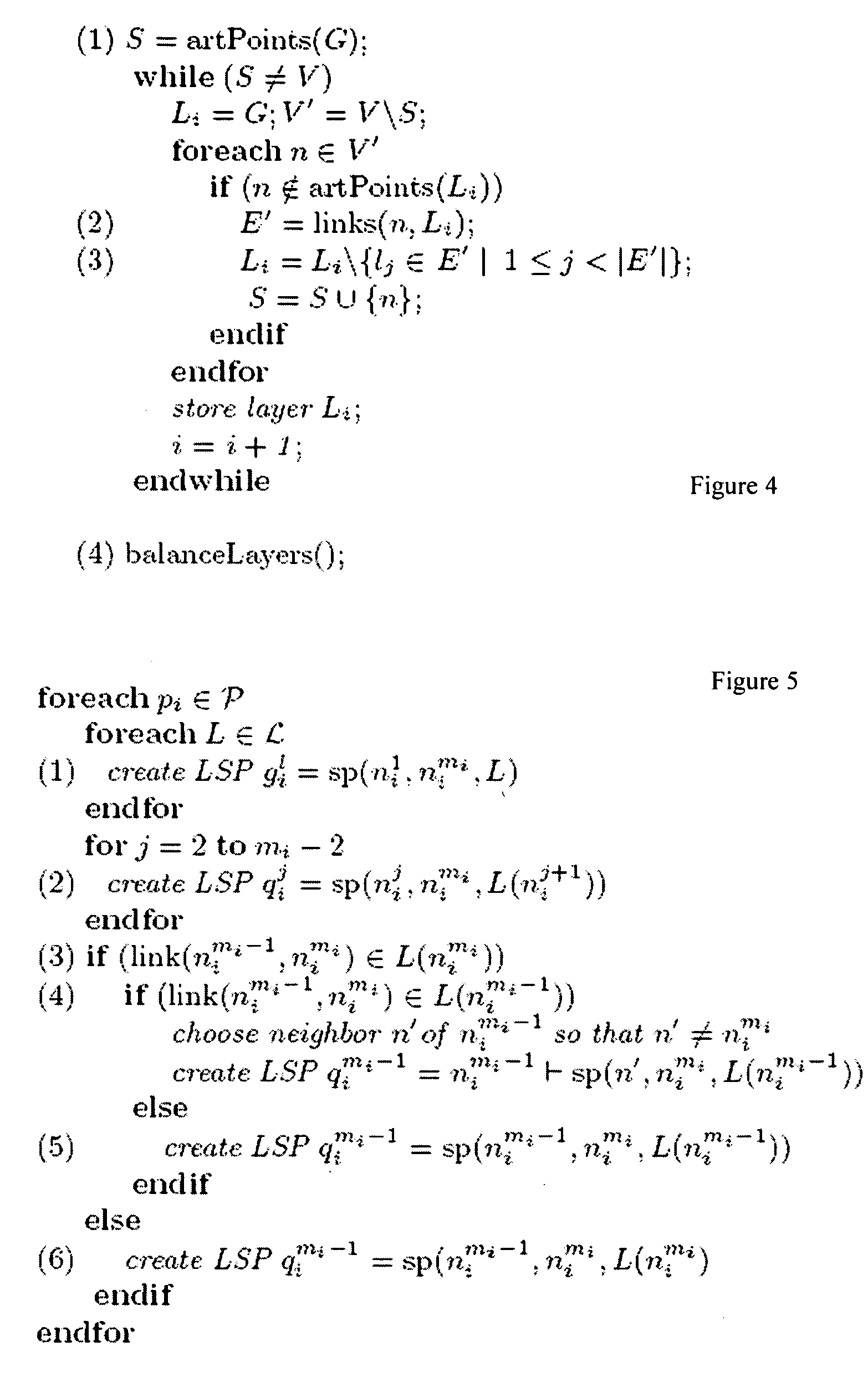
[0062]FIG. 4 shows a first algorithm;

[0063]FIG. 5 shows a second algorithm;

[0064]FIG. 6 shows a network configuration with an isolated node;

[0065]FIG. 7 shows a network configuration with an isolated node and a disabled link;

[0066]FIG. 8 shows a network configuration with a number of isolated nodes and inhibited or disabled links;

[0067]FIG. 9 shows a further embodiment of an algorithm;

[0068]FIG. 10 shows a notation table; and

[0069]FIG. 11 shows a flow diagram in implementation of the invention.

[0070] The first embodiment is referred to as “Resilient Routing Layers” (RRL) and is based on calculating redundant subsets of the network topology that are called layers. Each layer contains all nodes but only a subset of the link...


PUM


Abstract

A network comprises nodes and links. In addition to a default topology there are backup configurations. Each node is inhibited from transferring data between nodes in at least one backup configuration. When a node detects a fault in the reception of data transmitted to a neighbouring node, it switches to a backup configuration in which the neighbouring node is inhibited. In one arrangement a backup configuration has at least one link which is restricted by having a high weighting so that it transmits data to a node only if that node is the final destination node for that data. Additionally, if the neighbouring node is the final destination, and routing of data is still unsuccessful in the backup configuration, the detecting node selects and switches to an alternate backup configuration in which the detecting node is inhibited.

Description

RELATED APPLICATION [0001] This application claims priority from U.S. Provisional Patent Application 60 / 682,114 filed 17 May 2005.FIELD OF THE INVENTION [0002] This invention relates to the routing of data, for example packets or streams of data in a computer or communications network. [0003] Typically, such a network comprises nodes and links. Nodes are components which transmit, receive or route data, i.e. receive data and then transmit the data to another node. Nodes may comprise routers or other data processing apparatus. Links are the connections between nodes, over which the data is transmitted. These may be hard wired links, such as copper or optical fibre links, or may be wireless using, for example, microwaves or other forms of radio or other wireless transmission. [0004] In many environments it is critical that data continues to be transmitted over a network even though a node or a link fails. Network topologies are designed so that, as far as possible, if a node ceases to...

Claims


Application Information

Patent Timeline
IPC IPC(8): H04J3/14H04L12/56
CPCH04L45/00H04L45/28H04L45/22
Inventor LYSNE, OLAVKVALBEIN, AMUNDHANSEN, AUDUN FOSSELIEGJESSING, STEINCICIC, TARIK
Owner RESILIENS
Learn More