Magnetic circuit arrangement for a sensor

a technology of magnetic circuit and sensor, which is applied in the direction of mass flow measurement devices, measurement devices, instruments, etc., can solve the problems of inability to place, inability to bend too easily, and inability to achieve high degree of freedom, improve the manner of securement and arrangement, and improve the effect of reliability

Active Publication Date: 2006-04-20
ENDRESS HAUSER FLOWTEC AG
View PDF6 Cites 13 Cited by
  • Summary
  • Abstract
  • Description
  • Claims
  • Application Information

AI Technical Summary

Benefits of technology

[0025] An object of the invention is to improve the manner of securement and arrangement of the leads for magnetic circuit arrangements of a sensor of the described kind, especially those which can be used for fluids of high temperature, to the effect that the electrical supply leads exhibit a long life coupled simultaneously with a high and reliable number of cycles in fatigue testing, and that the securement itself is mechanically robust and of relatively simple construction, without decreasing the sensitivity of the sensor to the measured parameter to any extent worth mentioning.

Problems solved by technology

Apart from the fact that, by placing the leads directly on the sensing tube, the tube oscillation properties can be influenced, such placement is not even possible, when the sensor is to be used for measuring high temperature fluids.
On the other hand, however, the spring elements cannot be too difficult to bend, since, otherwise, an influencing of the bending oscillations of the sensing tubes, and, thus also, the sensitivity of the sensor to the parameter to be registered, becomes possible to an undesirably high extent.
In order to be able to satisfy all these requirements together, at least approximately, especially also to attain the required reliability, the spring elements become comparatively expensive to manufacture.
Then, there is the necessity for mounting them at very great technical effort onto the sensing tubes and, as mentioned above, onto the sensor housing, or the like.
Because of this, the electrical supply leads, too, only experience a negligibly small amount of oscillation-related bending loading during operation of the sensor.
However, it has been found in the case of this kind of magnetic circuit arrangement that especially the sensor signals produced therewith can be considerably corrupted, a fact which can, on the one hand, be related to the way in which the magnetic field is channeled, but, on the other hand, can also be traced back to parasitic vibrations of the magnetic circuit arrangement itself.

Method used


Image

  • Magnetic circuit arrangement for a sensor
  • Magnetic circuit arrangement for a sensor
  • Magnetic circuit arrangement for a sensor

Examples


Embodiment Construction

[0090] While the invention is susceptible to various modifications and alternative forms, exemplary embodiments thereof have been shown by way of example in the drawing and will herein be described in detail. It should be understood, however, that there is not intent to limit the invention to the particular forms disclosed, but, on the contrary, the intention is to cover all modifications, equivalents, and alternatives falling within the spirit and scope of the invention as defined by the appended claims.

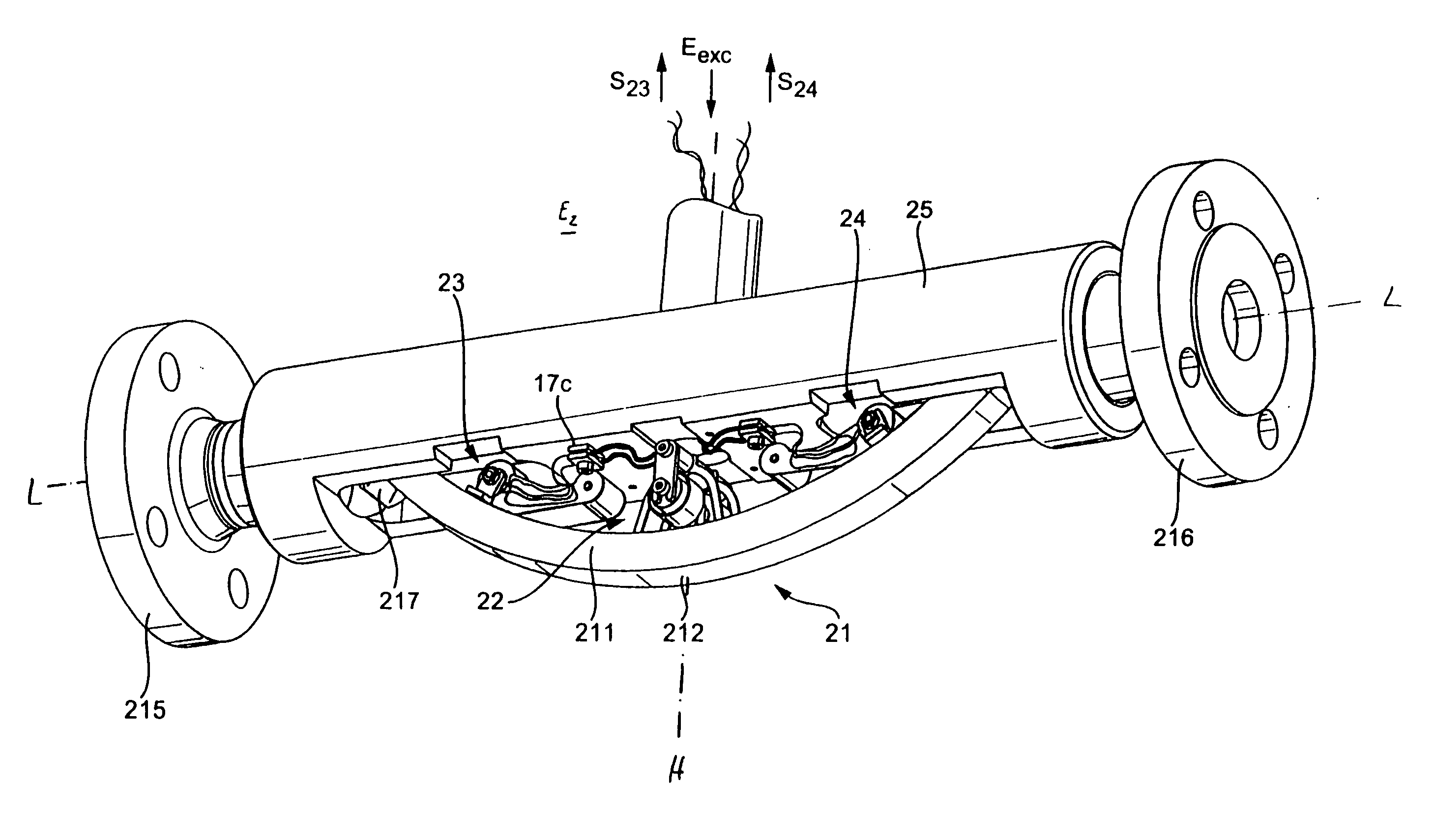
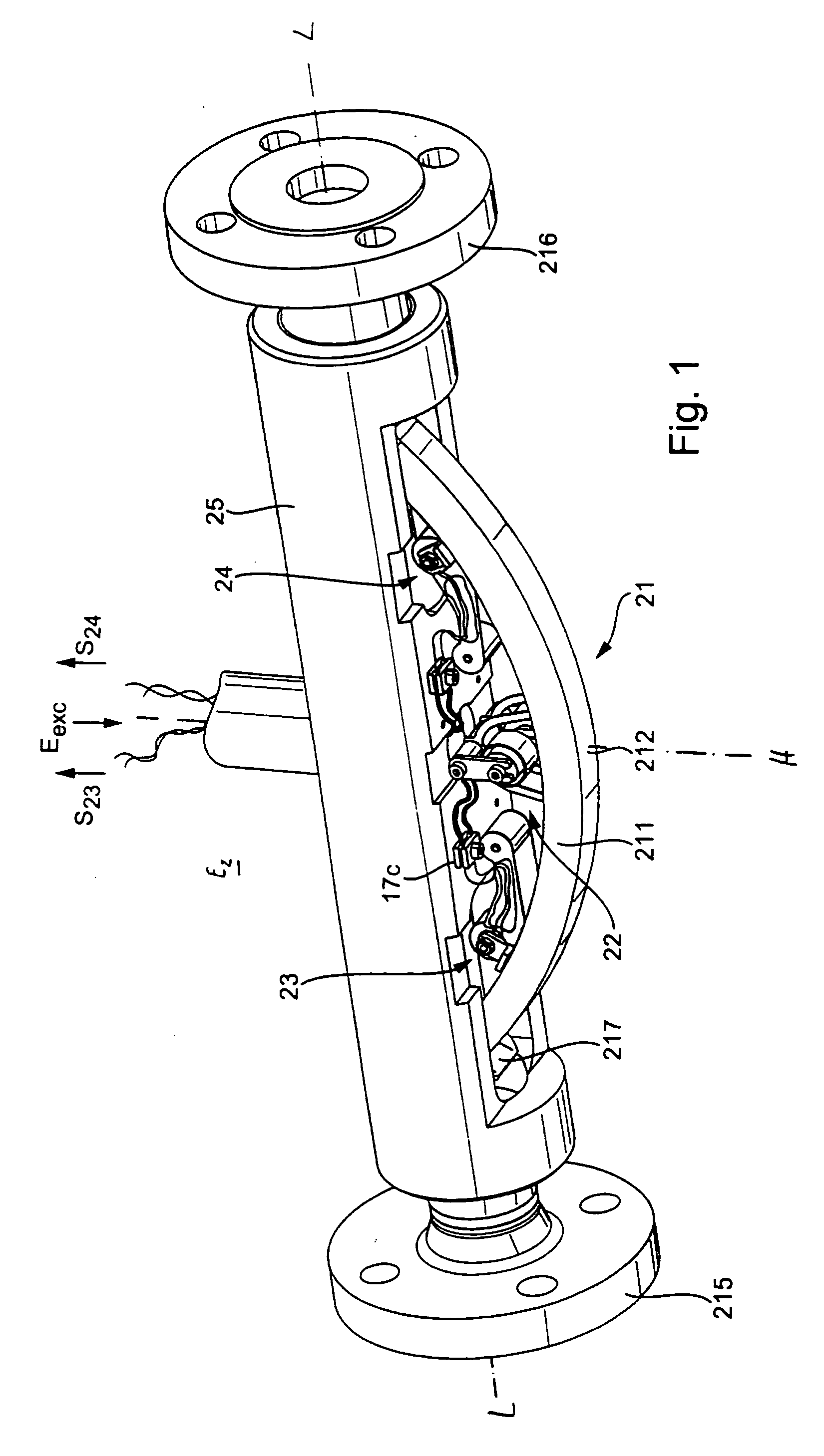
[0091]FIG. 1 shows an example of an embodiment of a vibration-type sensor, especially a Coriolis mass flow sensor, a Coriolis mass flow / density sensor, or also a viscosity / density sensor, or the like, which, by way of example, can be used for measuring a mass flow rate, a density and / or a viscosity of a fluid flowing in a pipe (not shown). Such a sensor serves, applied as a physical-electrical transducer in a corresponding measuring device, as is known, for the purpose of producing...


PUM


Abstract

A mount for electrical leads to a vibration-type sensor and / or for coils on a vibration-type sensor. The mount includes at least one resilient first arm attached to a first sensing tube of the sensor and at least one resilient arm attached to a second sensing tube of the sensor. The two sensing tubes, which are caused to vibrate during operation of the sensor, form a double-tube arrangement having a longitudinal gravity line, which lies in an imaginary central plane extending between the two, preferably parallel, sensing tubes. The two arms of the mount are essentially rigidly connected to one another at a connecting location remote from the two sensing tubes, and the mount exhibits a first eigenmode of predeterminable mechanical resonance frequency, f1, at which the first arm attached to the first sensing tube and the second arm attached to the second sensing tube oscillate pendularly essentially perpendicular to the central plane of the double-tube arrangement. The mount exhibits a second eigenmode of predeterminable mechanical resonance frequency, f2, at which the first arm attached to the first sensing tube and the second arm attached to the second sensing tube oscillate pendularly essentially parallel to the central plane of the double-tube arrangement, and the resonance frequency, f1, of the first eigenmode is different from the resonance frequency, f2, of the second eigenmode.

Description

[0001] This application claims the benefit of provisional application No. 60 / 463,055 filed on Apr. 16, 2003.FIELD OF THE INVENTION [0002] The invention relates to a magnetic circuit arrangement suited for use in a vibration-type sensor, especially a Coriolis mass flow sensor. BACKGROUND OF THE INVENTION [0003] For determining mass flow rate of a fluid flowing in a pipe, especially that of a liquid, Coriolis mass flow meters are often used. As is known, these meters cause Coriolis forces in the fluid by means of a corresponding vibration-type sensor, driven by a control- and evaluation-electronics connected thereto, and use these forces to produce a measurement signal representing the mass flow rate. [0004] Coriolis mass flow meters are long known and are used industrially. Examples of such meters are presented in EP-A 1 154 243, U.S. Pat. Nos. 4,876,898, 4,801,897, 5,048,350, 5,301,557, 5,394,758, 5,549,009, 5,796,011, and WO-A 02 / 099363, which describe Coriolis mass flow meters, ea...

Claims


Application Information

Patent Timeline
Patent Type & Authority Applications(United States)
IPC IPC(8): G01F1/84
CPCG01F1/8413G01F1/8427G01F1/8477
Inventor BITTO, ENNIOECKERT, GERHARD
Owner ENDRESS HAUSER FLOWTEC AG
Why Eureka
Try Eureka