Method for machining workpieces

a technology for workpieces and workpieces, applied in the direction of machining electric circuits, manufacturing tools, electric circuits, etc., can solve the problems of unusable surface damage on the workpiece and damage to the machining electrodes

Inactive Publication Date: 2006-04-20
MTU AERO ENGINES GMBH
View PDF3 Cites 2 Cited by
  • Summary
  • Abstract
  • Description
  • Claims
  • Application Information

AI Technical Summary

Benefits of technology

[0005] An object of the present invention is to provide a method which allows the distance between the workpiece and the machining electrode to be determined and regulated as precisely as possible in a particularly favorable way.

Problems solved by technology

A voltage discharge finally results in undesired surface damage occurring on the workpiece and the machining electrode also suffering damage.

Method used


Image

  • Method for machining workpieces
  • Method for machining workpieces
  • Method for machining workpieces

Examples


Embodiment Construction

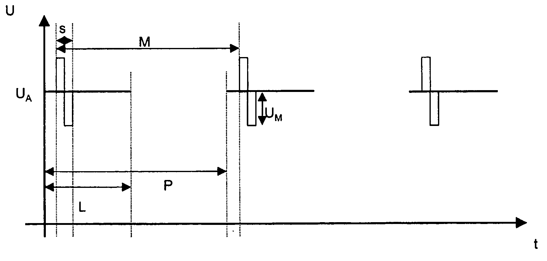
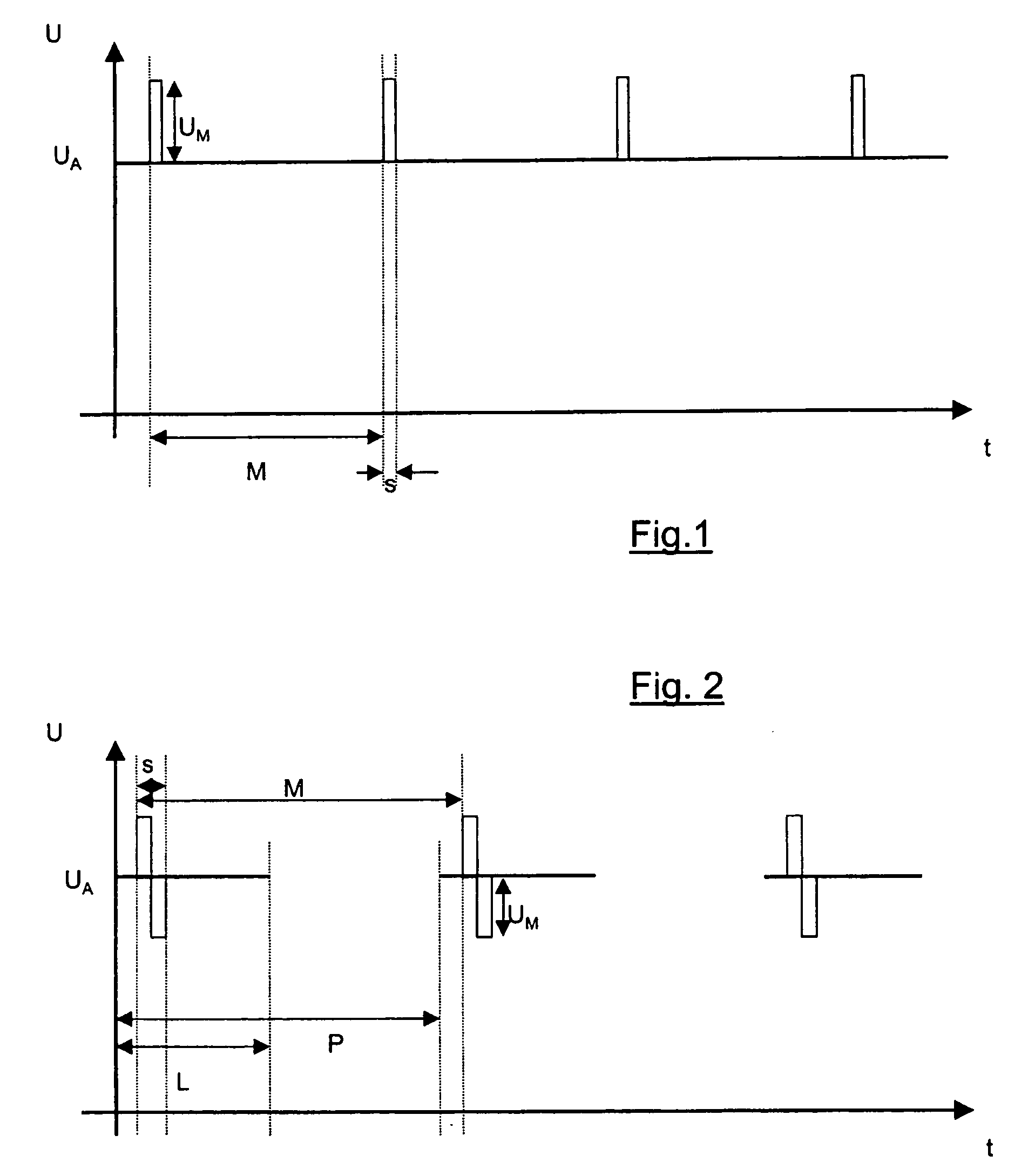
[0020]FIGS. 1 and 2 each show the diagram of the voltage curve over time, which is provided when performing the method according to the present invention. In the method according to the present invention, the voltage is produced at the machining electrode and the current flow resulting because of the production of the voltage is measured. The operating current resulting from the operating voltage is first filtered out of the current signal in a computer device, so that this current signal only contains the current component which is caused by the measuring voltage. This may be performed using a high-pass filter or other appropriate device, for example. Alternatively, the voltage production device for the measuring voltage can be separate from the voltage production device for the operating voltage, so that the resulting measuring current is directly measurable in the area of the voltage production device for the measuring voltage.

[0021] In any event, a corresponding value for the d...


PUM

PropertyMeasurementUnit
operating voltageaaaaaaaaaa
voltageaaaaaaaaaa
distanceaaaaaaaaaa

Abstract

A method for machining workpieces provides a machining electrode, which is guided at a specific distance to the workpiece. An electrolyte is provided between the workpiece and the machining electrode, through which an operating current flows between the machining electrode and the workpiece. The operating current results from an operating voltage (UA), which is produced at the machining electrode, the workpiece being connected to ground. To perform the machining procedure, the distance between the machining electrode and the workpiece is regulated and the operating voltage (UA) is determined in such a way that the resulting operating current is a DC current or a pulsed DC current—i.e., the operating voltage is a DC voltage of fixed or specific dimension. A measuring voltage (UM) is superimposed on the operating voltage (UA) for producing the operating current. The measuring current resulting because of the application of the measuring voltage (UM) is detected and the distance between the machining electrode and the workpiece is concluded from the relationship between the measuring voltage (UM) and the measuring current.

Description

[0001] This application claims priority to DE 10 2004 049 967.5 filed Oct. 14, 2004, the entire disclosure of which is hereby incorporated by reference. FIELD OF THE INVENTION [0002] The present invention relates to a method for machining workpieces in which a current flows from a machining electrode through an electrolyte to a workpiece. Background [0003] High precision surfaces may be produced via machining. In this case, the processing precision is a function in particular of how precisely the machining electrode is guided at the closest possible distance to the workpiece. The smaller the distance between the machining electrode and the workpiece, the smaller the zone in which an electrical field forms, and in which the current flow and the removal of material from the surface of the workpiece occur. [0004] To ensure good processing precision, it is important that the guiding of the machining electrode in relation to the workpiece is performed with the greatest possible precision...

Claims


Application Information

Patent Timeline
Patent Type & Authority Applications(United States)
IPC IPC(8): B23H7/18
CPCB23H3/02
Inventor BAYER, ERWINBUSSMANN, MARTINKRAENZLER, THOMASPLATZ, ALBINSTEINWANDEL, JUERGEN
Owner MTU AERO ENGINES GMBH
Why Eureka
Try Eureka