Heat dissipation structure of light-emitting diode

a technology of light-emitting diodes and heat dissipation structures, which is applied in the direction of lighting and heating apparatus, solid-state devices, transportation and packaging, etc., can solve the problems of large amount of heat generated, increased cost of heat sinks, and inability to properly process heat sinks, so as to achieve enhanced heat dissipation performance

Inactive Publication Date: 2012-12-13
SUNG WEN KUNG
View PDF15 Cites 7 Cited by
  • Summary
  • Abstract
  • Description
  • Claims
  • Application Information

AI Technical Summary

Benefits of technology

[0009]The primary objective of the present invention is to mount a heat dissipation frame to a package housing to allow a light-emitting chip that generates high temperature to be mounted on the heat dissipation frame. Opposite ends of the heat dissipation frame are bent downward to overlap a bottom surface of the heat dissipation frame, whereby when the light-emitting diode according to the present invention is mounted to a circuit board that is coupled with a heat dissipater, since the light-emitting chip is set in tight engagement with the heat dissipation frame, the high temperature generated by the light-emitting diode can be conducted to the heat dissipation frame and then to the heat dissipater for dissipation. The heat dissipation route is thus made a direct and shortest way, providing an enhanced heat dissipation performance for the high temperature generated by the light-emitting chip.
[0010]A secondary objective of the present invention is to provide a heat dissipation frame that is made through a single stamping operation applied to a single piece of raw material, whereby the constituent material is identical and the thickness is the same and is thus applicable to simultaneous stamping with all types of stamping machines that are currently available (such as a stamping press). Since a single piece of raw material is used, the amount of scrap can be reduced, making cost and consumption of material minimum and complying with the trend of environmental protection and simplifying and shortening the manufacturing process.
[0011]A further objective of the present invention is to provide various advantages of mass production and fast manufacturing through practicing an embodiment of the present invention.
[0012]Yet a further objective of the present invention is to provide an optimum way of heat dissipation through omission of additional heat dissipation element and eliminating mutual interference due to heat and electricity are separated.

Problems solved by technology

A common issue for these lighting devices is large amount of heat generated by the LED.
For the way of additionally mounting a heat sink, the heat sink increases the cost and the heat sink must be properly processed before the heat sink and the LED lighting device can be combined together.
An additional process is required and this extends the manufacturing time.
Further, for the way of stamping or scraping the conductive pins, the processing expense is high and the additional operation used to process the thickness of the conductive pins may be difficult to stamp or scrape the conductive pins to a small thickness.
This in turn extends the manufacturing time and increases the manufacturing cost.
Apparently, the conventional ways are both disadvantageous in certain respects and further improvement is desired.

Method used


Image

  • Heat dissipation structure of light-emitting diode
  • Heat dissipation structure of light-emitting diode
  • Heat dissipation structure of light-emitting diode

Examples


Embodiment Construction

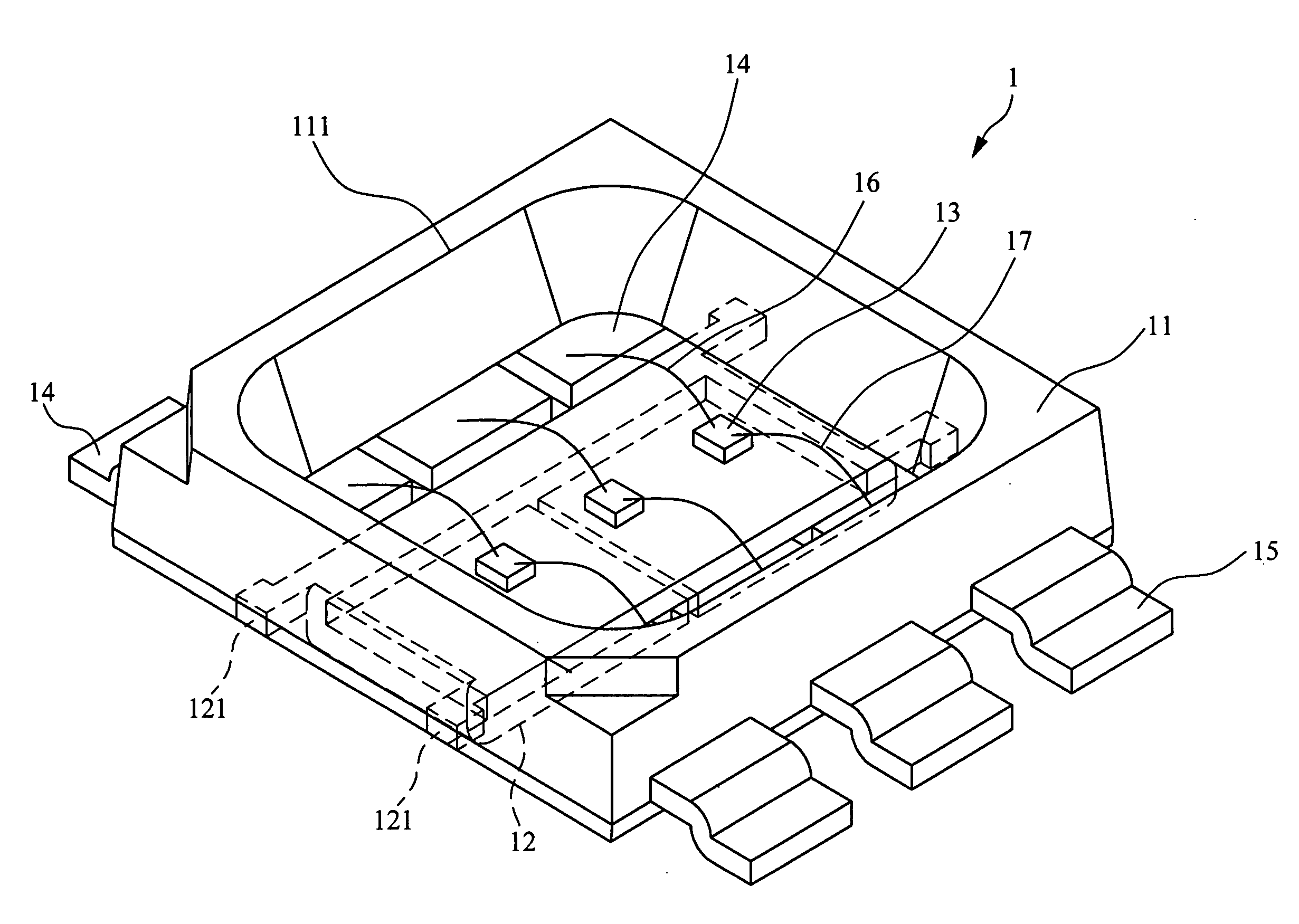
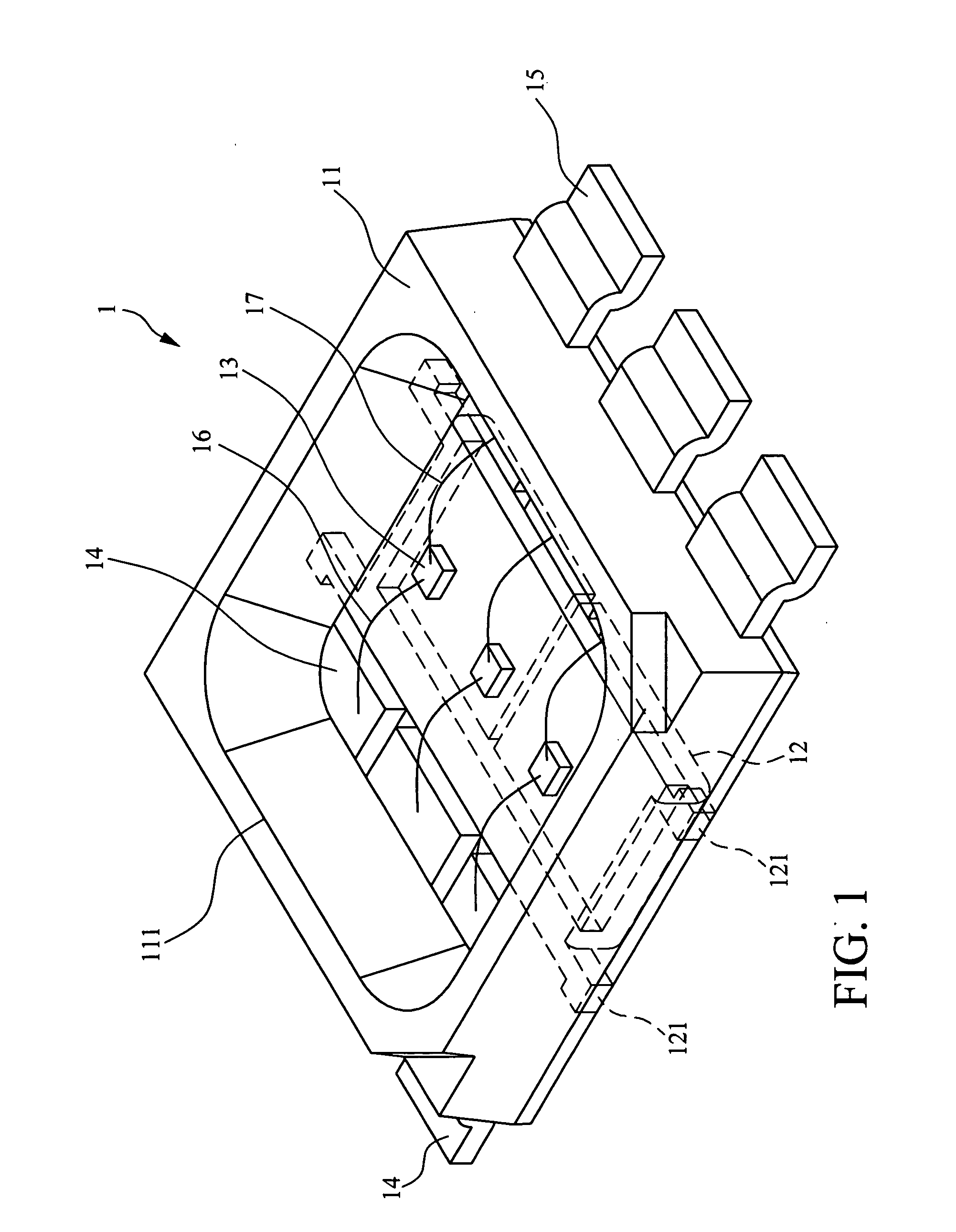
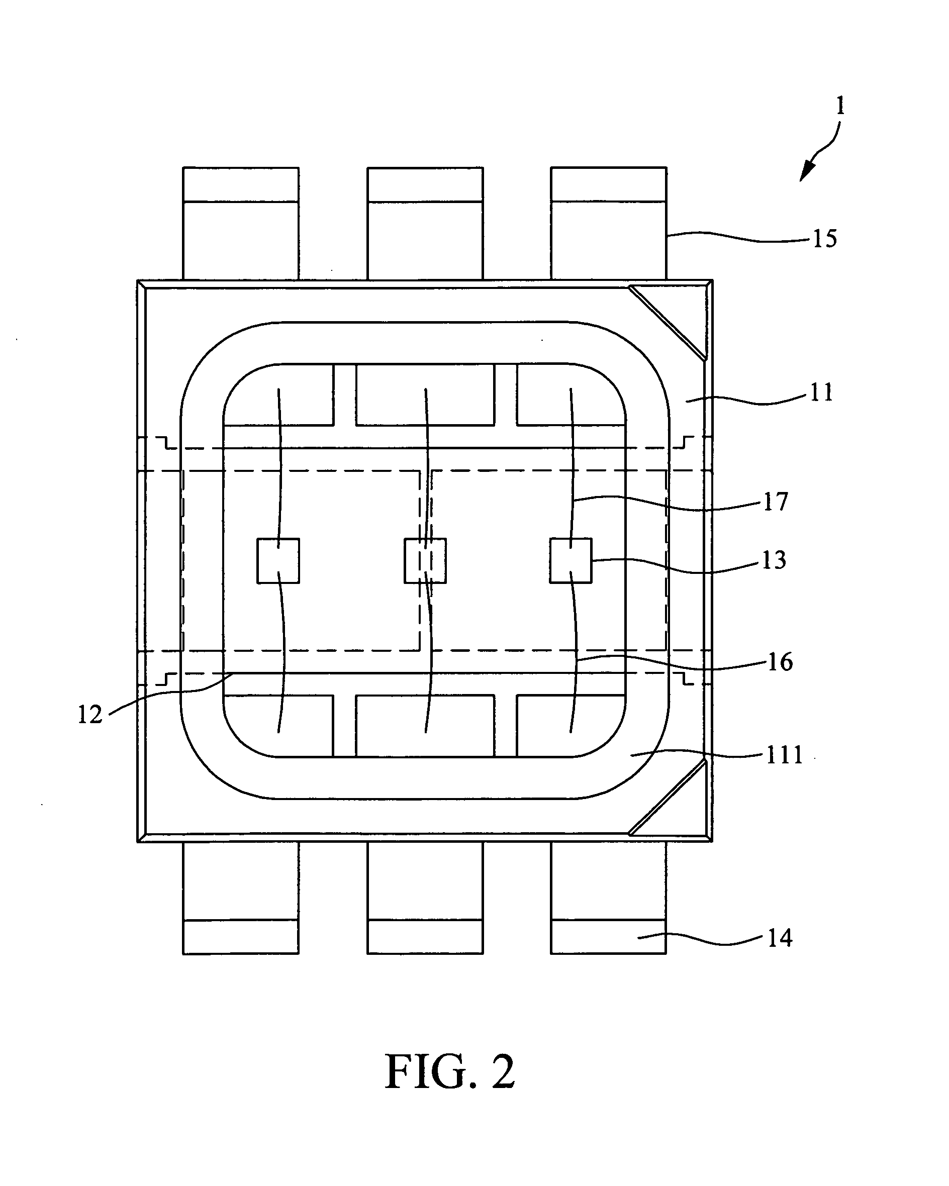
[0021]With reference to the drawings and in particular to FIGS. 1-3, which are different views of a heat dissipation structure of light-emitting diode according to the present invention, the light-emitting diode, generally designated at 1, comprises the following components:

[0022]A package housing 11 forms a recessed cavity 111.

[0023]At least one heat dissipation frame 12 is mounted in the recessed cavity 111 of the package housing 11 to have a portion thereof located inside the recessed cavity 111 of the package housing 11 and opposite ends of the heat dissipation frame 12 being bent downward to overlap a bottom surface of the heat dissipation frame 12, whereby the ends of the heat dissipation frame 12 are bent inward to a bottom surface of the package housing 11.

[0024]At least one light-emitting chip 13 is positioned on a desired location on the portion of the heat dissipation frame 12 inside the recessed cavity 111 of the package housing 11.

[0025]At least one first conductive pin...


PUM


Abstract

A heat dissipation structure of light-emitting diode includes a package housing, which forms a recessed cavity. A heat dissipation frame is mounted inside the recessed cavity of the package housing to have a portion of the heat dissipation frame located inside the recessed cavity of the package housing and opposite ends of the heat dissipation frame being bent downward to overlap a bottom surface of the heat dissipation frame. A plurality of light-emitting chips is set on the heat dissipation frame located inside the recessed cavity. A plurality of conductive pins is arranged in the recessed cavity of the package housing and extends outside opposite ends of the package housing through opposite end walls of the recessed cavity. A plurality of conductive wires respectively connects between the light-emitting chips and the conductive pins inside the recessed cavity to thereby form the heat dissipation structure of light-emitting diode.

Description

FIELD OF THE INVENTION[0001]The present invention relates to a heat dissipation structure of light-emitting diode, and in particular to a heat dissipation structure of light-emitting diode that comprises a heat dissipation frame mounted inside a package housing and having two ends that are downward bent to overlap a bottom surface of the heat dissipation frame.BACKGROUND OF THE INVENTION[0002]A variety of light-emitting diode (LED) based lighting devices are available in the market. A common issue for these lighting devices is large amount of heat generated by the LED. The heat must be dissipated from the LED lighting devices. A major research direction of the LED industry is to eliminate excessive high temperature that might shorten the lifespan of the devices.[0003]Two major types of constructions are currently used for LED lighting devices, which will be briefly described as follows:[0004](1) A heat sink is arranged between the LED lighting device and a circuit board so that the ...

Claims


Application Information

Patent Timeline
Patent Type & Authority Applications(United States)
IPC IPC(8): F21V29/00
CPCH01L25/0753H01L33/62H01L2224/48247H01L33/647H01L33/642
Inventor SUNG, WEN-KUNG
Owner SUNG WEN KUNG
Why Eureka
Try Eureka