Contaminated liquids filtering apparatus

a technology of filtering apparatus and liquid, which is applied in the direction of moving filter element filter, filtration separation, and separation process, etc., can solve the problems of large surface area, erosion of engine performance, and contamination of engine liquid fuel, and achieve the effect of efficient filtering large reserves of contaminated liquid

Inactive Publication Date: 2006-04-20
YEE PHILIP W +1
View PDF24 Cites 25 Cited by
  • Summary
  • Abstract
  • Description
  • Claims
  • Application Information

AI Technical Summary

Benefits of technology

[0009] Another principal object of the invention is to provide a filtering apparatus that can efficiently filter large reserves of contaminated liquids in an ...

Problems solved by technology

Often, by-products of the internal combustion engine, such as acid, moisture, sludge, and dust particles, contaminate the liquid fuel of such an engine.
This results in the erosion of the performance of the engine.
In addition, conventional filters only allow the contaminated liquid to flow through the filter in a straight-line motion.
Thus, such filters require a large surface area, require frequent replacement, and may obstruct the flow of the circulating liquids.
As a result, more contaminants are trapped because the contaminated liquid passes through multiple layers of filter paper.
However, it is difficult to adapt such filters to accommodate for other a...

Method used


Image

  • Contaminated liquids filtering apparatus
  • Contaminated liquids filtering apparatus
  • Contaminated liquids filtering apparatus

Examples


Embodiment Construction

[0032] The description above and below and the drawings of the present document focus on one or more currently preferred embodiments of the present invention and also describe some exemplary optional features and / or alternative embodiments. The description and drawings are for the purpose of illustration and not limitation. Those of ordinary skill in the art would recognize variations, modifications, and alternatives. Such variations, modifications, and alternatives are also within the scope of the present invention. Section titles are terse and are for convenience only.

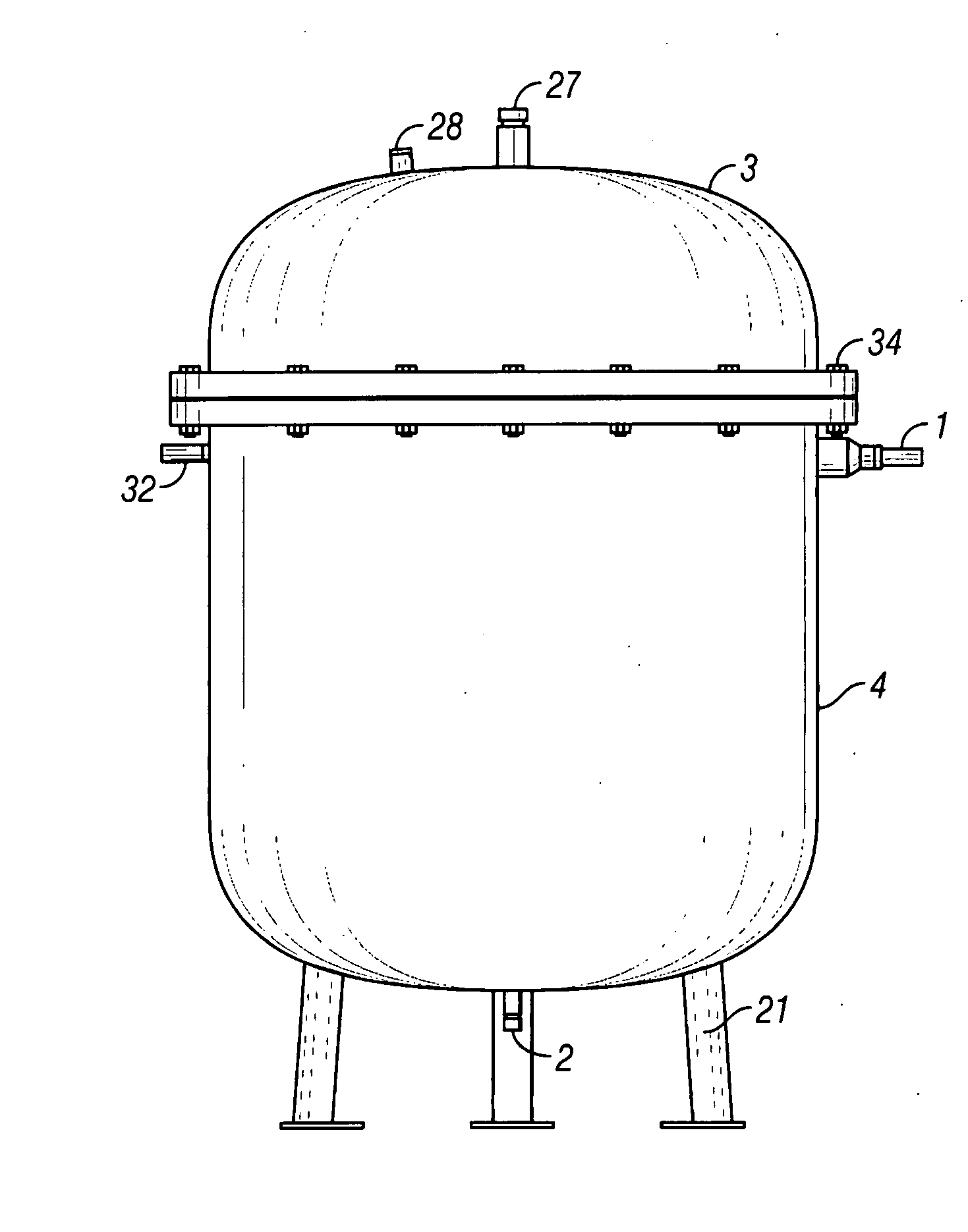
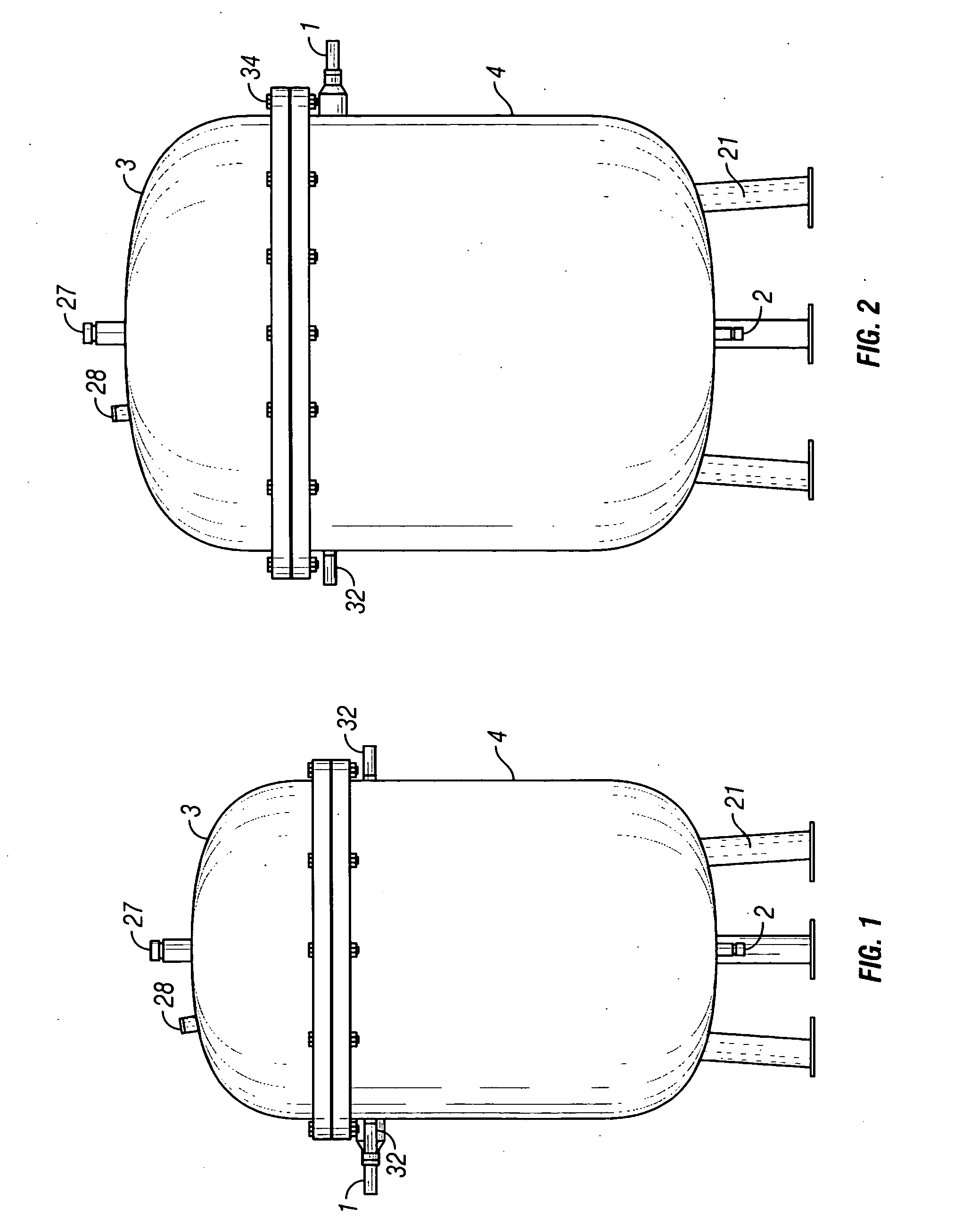
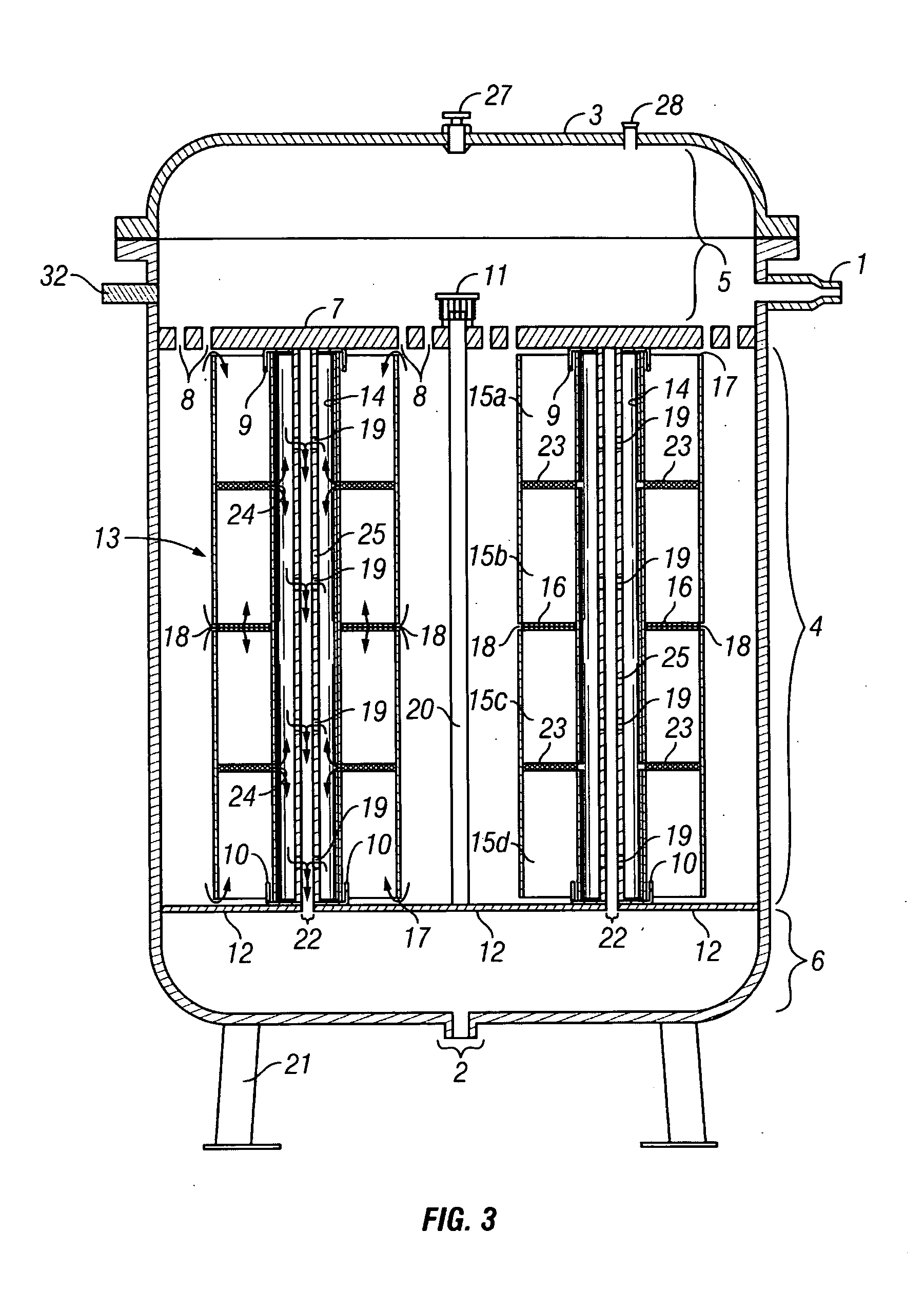
[0033] As shown in FIG. 1, a filtering apparatus comprises a removable upper lid 3, an elongate container body 4, an inlet 1, an outlet 2, and two or more filter units 13 situated inside the elongate container body 4. The elongate container body 4 has an upper end and a lower end. As used hereinafter and in the claims, all references to upward and downward directions will be made in reference to the orientation in F...


PUM

PropertyMeasurementUnit
Lengthaaaaaaaaaa
Thicknessaaaaaaaaaa
Pressureaaaaaaaaaa

Abstract

A filtering apparatus comprising an elongate container body, an inlet, an inlet reservoir, an outlet, an outlet reservoir, and at least two filter elements, wherein each filter units contains two or more space-apart and co-axially stacked filter elements encased in a cylindrical-shaped filter cartridge. Contaminated fluid flows from the inlet, through the perforations located on the inlet reservoir separator, and into the elongate container body. Fluid flows into the filter units through perforations in the filter cartridge and the open ends of the filter cartridge. The filter units use an opposed axial flow method to draw the fluid through the filter elements. The filtered fluid flows through a perforation in the axial conduit, passes through the axial conduit outlet into the outlet reservoir. The filtered fluid then exits through the outlet. The present invention may be used in operation with a motor and pump to filter large flow rates and volumes of contaminated fluid.

Description

BACKGROUND OF THE INVENTION [0001] 1. Field of the Invention [0002] The present invention relates generally to filtering devices, and more particularly, to a filtering apparatus comprised of a plurality of opposed axial flow filtering elements, each having a plurality of co-axially arranged filtering units. [0003] 2. Background of the Invention [0004] Often, by-products of the internal combustion engine, such as acid, moisture, sludge, and dust particles, contaminate the liquid fuel of such an engine. This results in the erosion of the performance of the engine. A filtration method can trap and remove such contaminates from the circulating liquid fuel. Most conventional filters sold on the market use a thin layer of porous membrane or paper. The finer the pores on the filter paper, the greater the amount of contaminants trapped and removed by the filter. Generally, such filters are attached to the internal combustion engine so that the liquid fuel is carried from the engine to the f...

Claims


Application Information

Patent Timeline
IPC IPC(8): B01D35/147
CPCB01D29/055B01D2201/0453B01D29/52B01D29/54B01D29/925
Inventor YEE, PHILIP W.YEE, SKIPPER K.
Owner YEE PHILIP W
Why Eureka
Try Eureka