Batch-continuous process and reactor

a technology of continuous process and reactor, applied in the direction of chemistry apparatus and processes, multi-stage water/sewage treatment, water/sludge/sewage treatment, etc., can solve the problems of complex operation, inability to use reliable time dependent control, and inability to use probes for measuring efficiency

Inactive Publication Date: 2006-04-20
KHUDENKO BORIS M
View PDF1 Cites 81 Cited by
  • Summary
  • Abstract
  • Description
  • Claims
  • Application Information

AI Technical Summary

Benefits of technology

[0012] The apparatus can be provided with a means for interrupting the discharge of the liquid and the solids. The apparatus can be further provided with means for recirculating the liquid and the solids. The means for recirculating can be pumps, airlifts, mixers, mechanical aerators, diffused air aerators, flow ejectors, and combinations thereof. The floating apparatus can be provided with support floats and with landing gear for proper positioning of the filtration and biofiltration equipment (tertiary treatment equipment) in a drained or partially drained reactor.

Problems solved by technology

A complex operation is the main disadvantage of the batch processes: the end of each process step needs to be determined and the change from one step to another needs to be executed.
Probes for measuring efficiency are either non-existent or very expensive.
Accordingly, less reliable time dependent controls are used.
Present day automation systems alleviate the operation problems but do not eliminate them.
A more complex reactor-and-clarifier design is the main disadvantage of the continuous processes as compared to batch processes.
Present day membrane systems apparently simplify the biological treatment system, however, these filtration systems are very expensive and difficult to operate.

Method used


Image

  • Batch-continuous process and reactor
  • Batch-continuous process and reactor
  • Batch-continuous process and reactor

Examples


Embodiment Construction

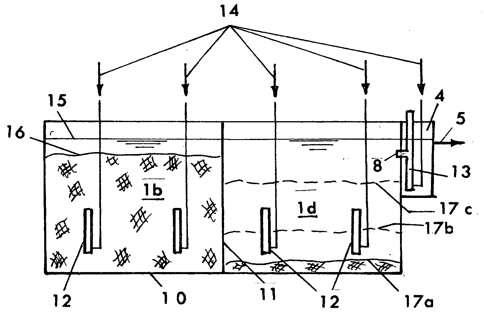
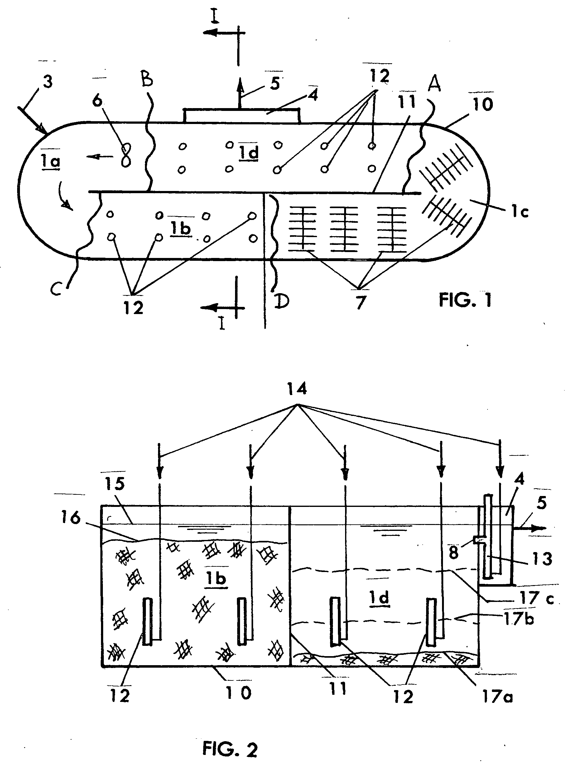
[0023] As an example of the process, a biological wastewater treatment process is considered herein.

[0024] Referring now to FIGS. 1 and 2, there is shown the basic system for conducting the present invention. The system includes a tank 10 with a baffle (inside wall) 11. The tank is divided into zones 1a, 1b, and 1c defined above as predominantly mixed (or contact) zones, and 1d representing predominantly unmixed zone. The top of the water is shown by line 15. Zone 1a may be at least periodically mixed by a propeller mixer 8 which simultaneously moves and recirculates the contents of the tank as shown by arrows. Other means for mixing and propelling can be used, for example,: pumps, airlifts. Design of such means presents no problems to those skilled in art. Lines 3 and 5 are respectively the influent and the effluent lines The influent line 5 is connected to an effluent box 4. Zone 1b may be anaerobic zone with considerably dense sludge at concentration up to 20 to 30 g / L. This zon...


PUM

PropertyMeasurementUnit
concentrationaaaaaaaaaa
oxidation-reduction conditionsaaaaaaaaaa
timeaaaaaaaaaa

Abstract

This is a method of batch-continuous operation for treatment and separation of liquid-solid mixtures in a reactor with reactive solids comprising steps of continuously feeding the liquid in the reactor, contacting (possibly, mixing) liquid with the solids in at least a portion of the reactor, periodically separating the liquid from the solids in unmixed, or predominantly unmixed, portion of the reactor, discharging at least a portion of the separated liquid from the reactor, and retaining the separated solids in the unmixed portion of the reactor, and periodically resuspending the solids in the unmixed portion of the reactor and transferring the resuspended soilds into the portion of the reactor for contacting liquid with the solids. The contacting and / or mixing of the liquid with the solids in the mixed portion of the reactor can be continuous or periodic mixing. The unmixed zone differs from the quiescent zone in conventional clarifiers. It is a flow-through zone with a noticeably high velocity of flow as in aeration tanks of biological treatment systems. The retention time in unmixed zones is much shorter than in clarifiers. The method and apparatus can be used to treat water and wastewater, and in various chemical, biochemical, and pharmaceutical processing operations.

Description

FIELD OF INVENTION [0001] This is a method and apparatus for batch-continuous operation of chemical, physical-chemical, and biological processes involving liquids and suspended particulate materials, the method can be applied in water and wastewater treatment, chemical manufacturing, pharmaceutical industries, petrochemical processing, and other like industries. PRIOR ART [0002] Continuous and batch processes involving liquids and suspended particles that need to be separated from liquids are well known. For example, the original biological wastewater treatment processes were batch operations including steps of filling wastewater into a tank containing active biomass (activated sludge), treating the wastewater by mixing the fed batch of wastewater with the biomass in the tank, settling the biomass under quiescent conditions and forming a clear layer of the treated wastewater on the top of the tank, decanting at least a portion of the clear layer, and repeating the sequence of these ...

Claims


Application Information

Patent Timeline
Patent Type & Authority Applications(United States)
IPC IPC(8): C02F3/00
CPCC02F3/06C02F3/10C02F3/1257C02F3/301Y02W10/10
Inventor KHUDENKO, BORIS M.
Owner KHUDENKO BORIS M
Why Eureka
Try Eureka