In-magnetic-field heat-treating device

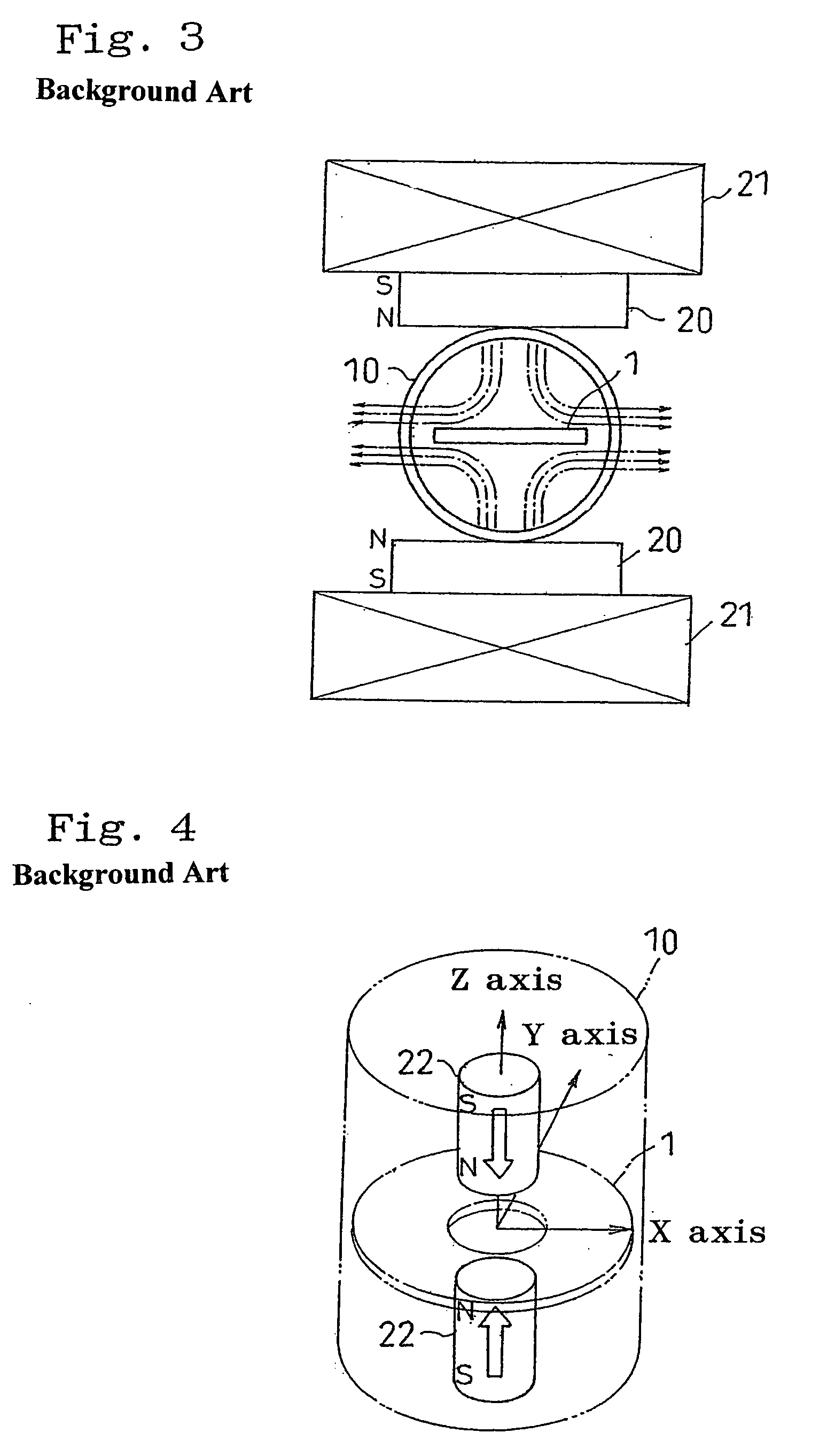
a heat treatment device and magnetic field technology, applied in the field of magnetic annealing devices, can solve the problems of increasing the size of the device, not providing a horizontal precision of the magnetization direction at a position where the soft magnetic film is, and the constitution of the magnetic circuit shown in fig. 4 was not good enough to satisfy the expected horizontal precision so as to achieve the effect of further improving the horizontal property of the magnetization direction

Inactive Publication Date: 2006-04-20
HITACHI METALS LTD +1
View PDF8 Cites 8 Cited by
  • Summary
  • Abstract
  • Description
  • Claims
  • Application Information

AI Technical Summary

Benefits of technology

[0017] When the second ferromagnetic substance is provided, the horizontal property of the magnetization direction can be further improved.

Problems solved by technology

However, in the constitution of the device shown in FIG. 3, the magnetic circuit is disposed outside the chamber 10, which does not provide a horizontal precision of the magnetization direction at a position where the soft magnetic film is disposed.
The constitution further includes the problem that the disposition of the components constituting the magnetic circuit on the outer side of the chamber 10 leads to an increased size of the device.
Yet, the constitution of the magnetic circuit shown in FIG. 4 was not good enough to satisfy an expected horizontal precision of the magnetization direction.

Method used


Image

  • In-magnetic-field heat-treating device
  • In-magnetic-field heat-treating device
  • In-magnetic-field heat-treating device

Examples


first embodiment

Constitution

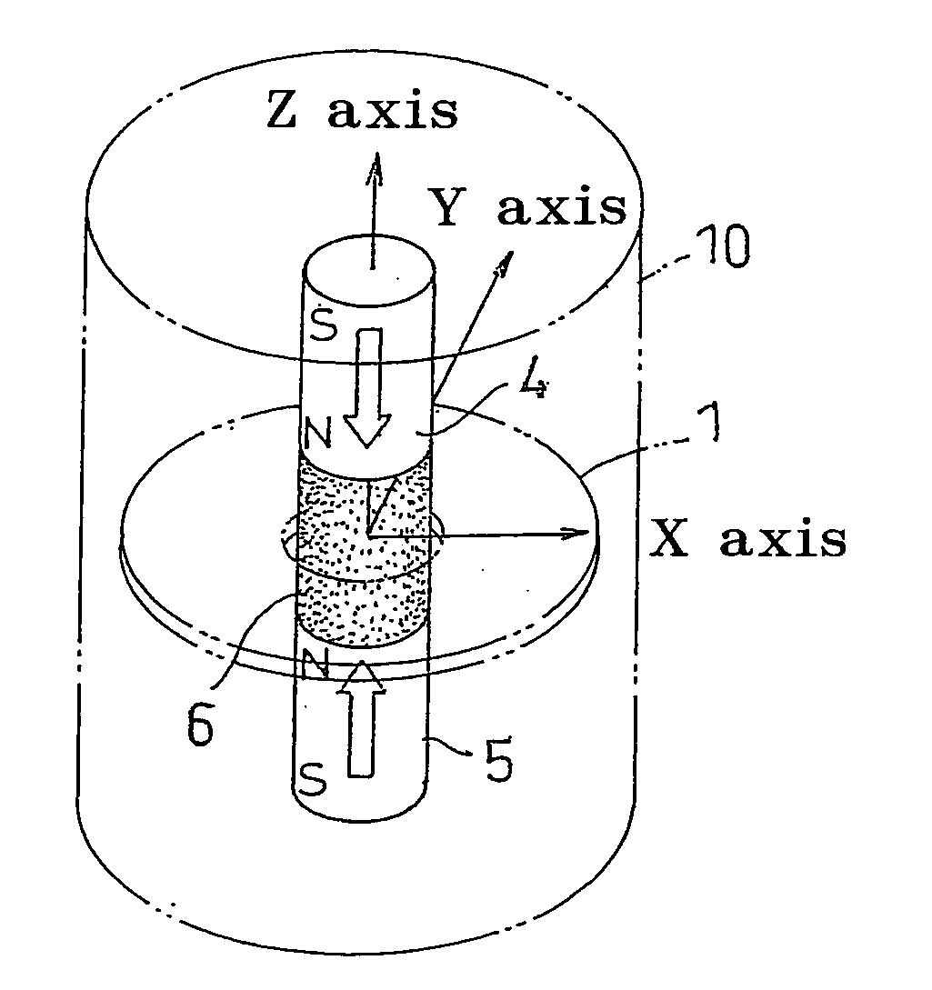
[0032] In FIG. 1, a pair of permanent magnets 4 and 5 is disposed in a chamber 10 so as to oppose their magnetic fields directionally to each other (shown in arrows). The permanent magnets 4 and 5 have a cylindrical shape. A first ferromagnetic substance 6 having the same cylindrical shape is disposed between the pair of permanent magnets 4 and 5. Respective end surfaces (N-pole side) of the permanent magnets 4 and 5 and both end surfaces of the first ferromagnetic substance 6 are in close contact with each other when they are disposed. Further, the permanent magnets 4 and 5 and the first ferromagnetic substance 6 have an identical axial direction and outer diameter dimension in their cylindrical bodies. According to the foregoing constitution, a magnetic flux leakage is minimized.

[0033] A recording medium 1 to be heat-treated is shown by an imaginary line in FIG. 1. The recording medium 1 has a disk shape and is provided with an axial hole formed at a center thereof. T...

second embodiment

Constitution

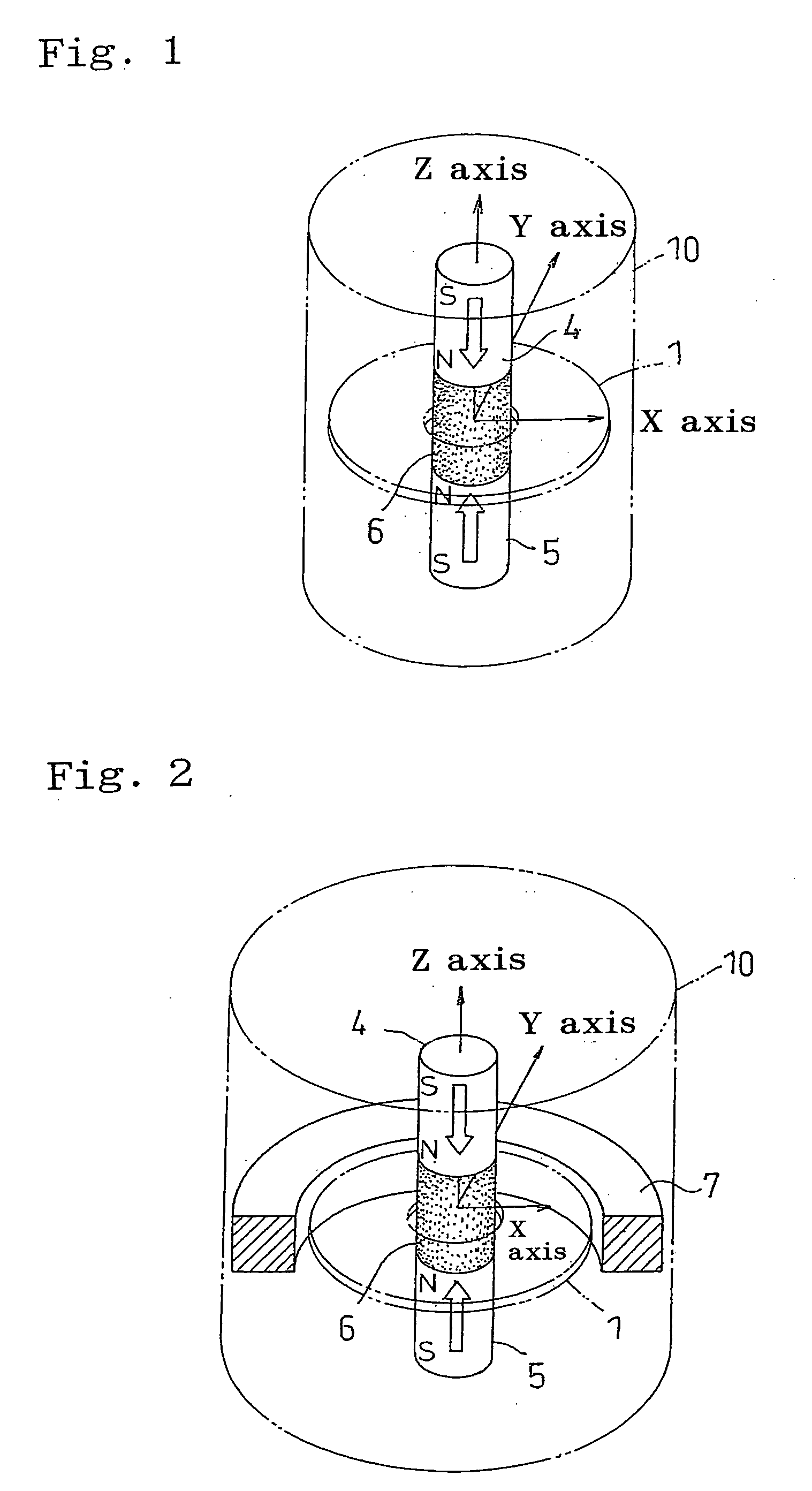
[0039] Next, a magnetic annealing device according to a second embodiment of the present invention is described referring to FIG. 2. A distinguishing difference between the constitutions of FIGS. 1 and 2 is the disposition of a second ferromagnetic substance 7 having a ring shape at a position in an outer periphery of the recording medium 1 (on an outer side of an end surface of the disk). The rest of the constitution is the same as in the first embodiment. The second ferromagnetic substance 7 can employ the same material as in the first ferromagnetic substance 6. A thickness of the second ferromagnetic substance 7 is preferably made thinner than the thickness of the first ferromagnetic substance 6 and approximately set to 1 / 1.5-⅛ of the thickness of the first ferromagnetic substance 6. The second ferromagnetic substance 7 having the ring shape can converge the magnetic leakge flux in the predetermined magnetic-field space. The horizontal element of the magnetization dir...


PUM

PropertyMeasurementUnit
temperatureaaaaaaaaaa

Abstract

A magnetic annealing device for inserting a recording medium 1 provided with an axial hole formed at a center thereof and having a disk shape into a chamber 10 and applying a heat treatment to the recording medium 1 in a magnetic field is provided with a magnetic circuit for forming a magnetic field in the chamber 10, the magnetic circuit comprises a pair of magnets 4 and 5 disposed with a distance therebetween along an axial direction of the axial hole and having magnetic fields directionally opposed to each other and a first ferromagnetic substance 6 disposed between the pair of magnets 4 and 5, wherein the recording medium 1 to be heat-treated is disposed at an intermediate position between the pair of magnets 4 and 5 facing each other in the state in which the first ferromagnetic substance 6 is inserted into the axial hole. A second ferromagnetic substance 7 having a ring shape is preferably disposed in a periphery of the recording medium 1.

Description

BACKGROUND OF THE INVENTION [0001] 1. Field of the Invention [0002] The present invention relates to a magnetic annealing device for inserting a recording medium provided with an axial hole at a center thereof and having a disk shape into a chamber and applying a heat treatment to the recording medium in a magnetic field. [0003] 2. Description of the Related Art [0004] As a method of recording data on a recording medium, such as a hard disk, is known a vertical magnetic recording method. The vertical magnetic recording method has a potential of remarkably increasing a recording density in comparison to a longitudinal-direction recording method and, therefore, is a technology attracting an attention. FIG. 5 illustrates a specific example associated with a magnetic head and a recording medium used in the vertical magnetic recording method. In FIG. 5, a main magnetic pole 2 and an auxiliary magnetic pole 3 are disposed so as to sandwich a recording medium. The recording medium 1 compri...

Claims


Application Information

Patent Timeline
Patent Type & Authority Applications(United States)
IPC IPC(8): C21D9/00C21D1/04H01F1/00G11B5/852
CPCG11B5/852
Inventor SUGIYAMA, EIJIAOKI, MASAAKIKENJU, HIROYUKIUTSUMI, RYOUICHIITAGAKI, KIICHI
Owner HITACHI METALS LTD
Why Eureka
Try Eureka