

Light emitting devices with mixed phosphors
Patent Information
- Authority / Receiving Office
- US · United States
- Current Assignee / Owner
- PHOSPHORTECH
- Publication Date
- 2006-04-20
- Estimated Expiration
- Not applicable · inactive patent
Smart Images
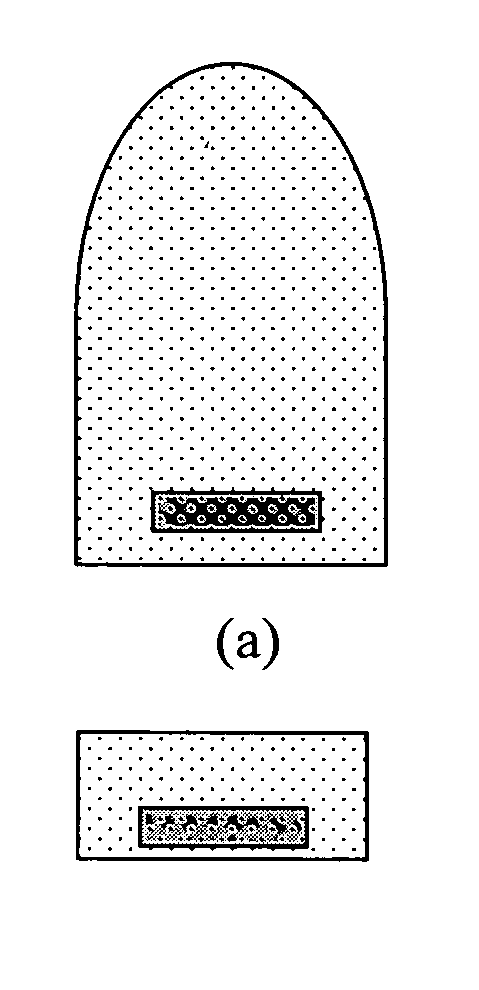
Figure 1 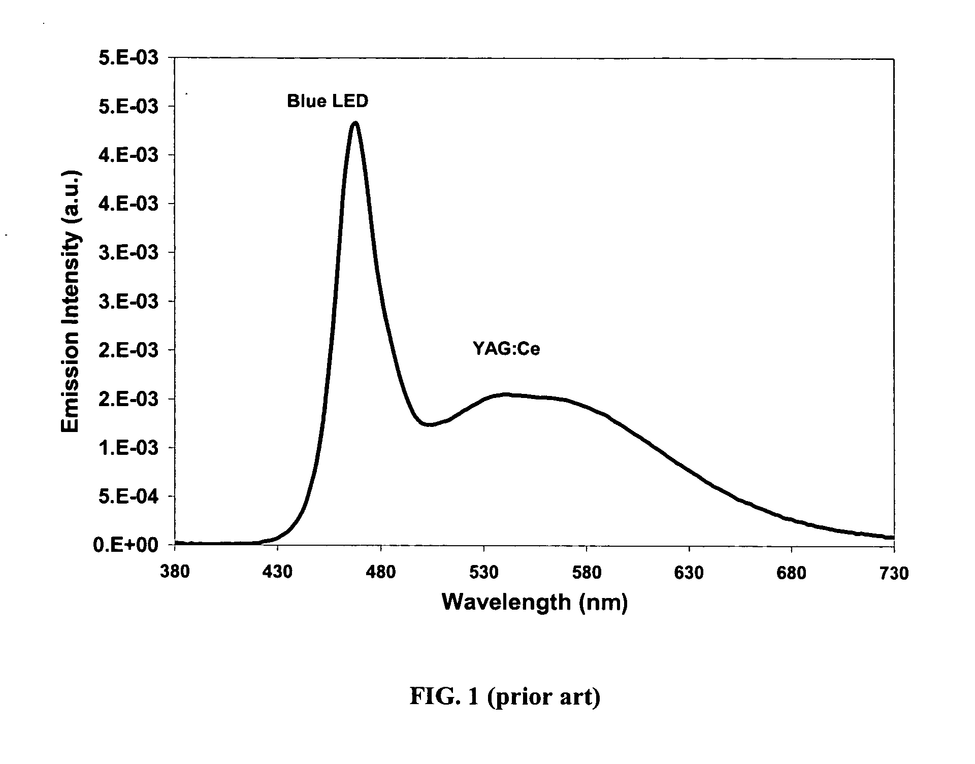
Figure 2 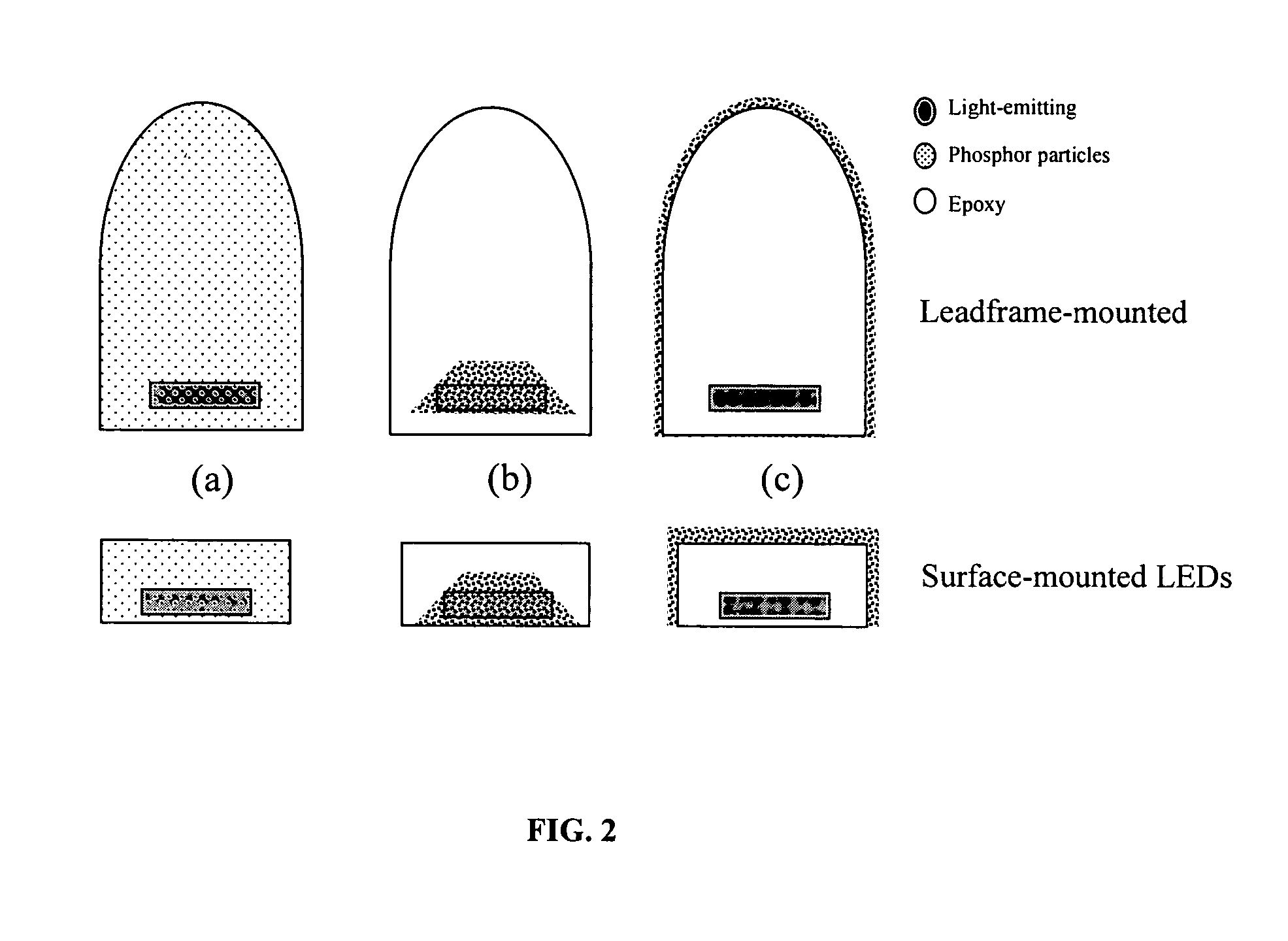
Figure 3
Abstract
Description
CROSS-REFERENCE TO RELATED APPLICATIONS
[0001] This application is a Continuation-In-Part of U.S. patent application Ser. No. 10 / 661,931 filed on Sep. 15, 2003; Ser. No. 10 / 801,067 filed Mar. 15, 2004; Ser. No. 10 / 801,082 filed Mar. 15, 2004, all currently still pending, and to U.S. provisional patent application Ser. No. 60 / 492,008 filed Aug. 2, 2003, the entire contents of all of which are herein incorporated fully by reference thereto.TECHNICAL FIELD
[0002] The present invention relates generally to solid-state light-emitting devices. More particularly, it relates to light emitting diodes, electroluminescent devices, and the like which comprise improved solid state materials having enhanced performance and efficiency over similar devices of the prior art. BACKGROUND INFORMATION
[0003] There have been few major improvements in conventional lighting (i.e. incandescent, halogen, and fluorescent lamps) over the past 20 years. However, in the case of light emitting diodes (“LEDs”), op...