Advanced electromagnetic location of electronic equipment

Active Publication Date: 2006-04-20
NOKOMIS
View PDF2 Cites 71 Cited by
  • Summary
  • Abstract
  • Description
  • Claims
  • Application Information

AI Technical Summary

Benefits of technology

[0021] Yet still another object of the present invention is to provide a method of and an apparatus such that when oscillators are the emission source for one spectral component of the signature it is possible to perturb the oscillator's emissions signature by illuminating the device with RF or microwave at the same frequency or at the frequency of its harmonics and in this manner as the secondary source is scanned across the device the signature change can be used to precisely locate the device with more accuracy than current direction and range finding technology including the illumination of the emissions of semiconductors as well and which may in many cases actually be leveraged to a greater extent.
[0022] It is a still further object of the present invention to provide a method of and an apparatus in which in addition to

Problems solved by technology

Unfortunately, as is equally well known, some electronic devices can be and ofte

Method used


Image

  • Advanced electromagnetic location of electronic equipment
  • Advanced electromagnetic location of electronic equipment
  • Advanced electromagnetic location of electronic equipment

Examples


Embodiment Construction

[0042] Prior to proceeding to the more detailed description of the invention it should be noted that identical components which have identical functions have been designated with identical reference numerals throughout the several views illustrated in the drawings for the sake of clarity.

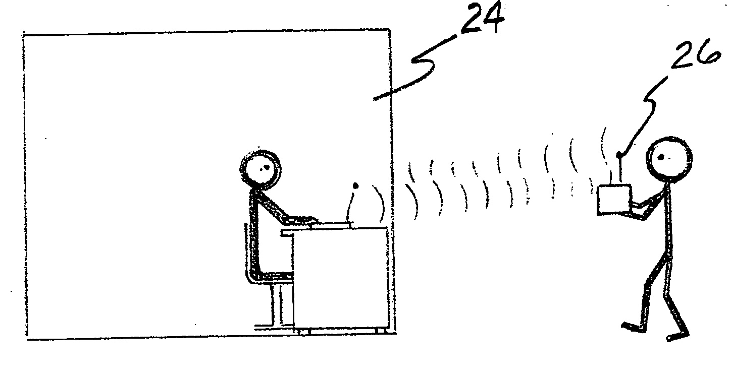
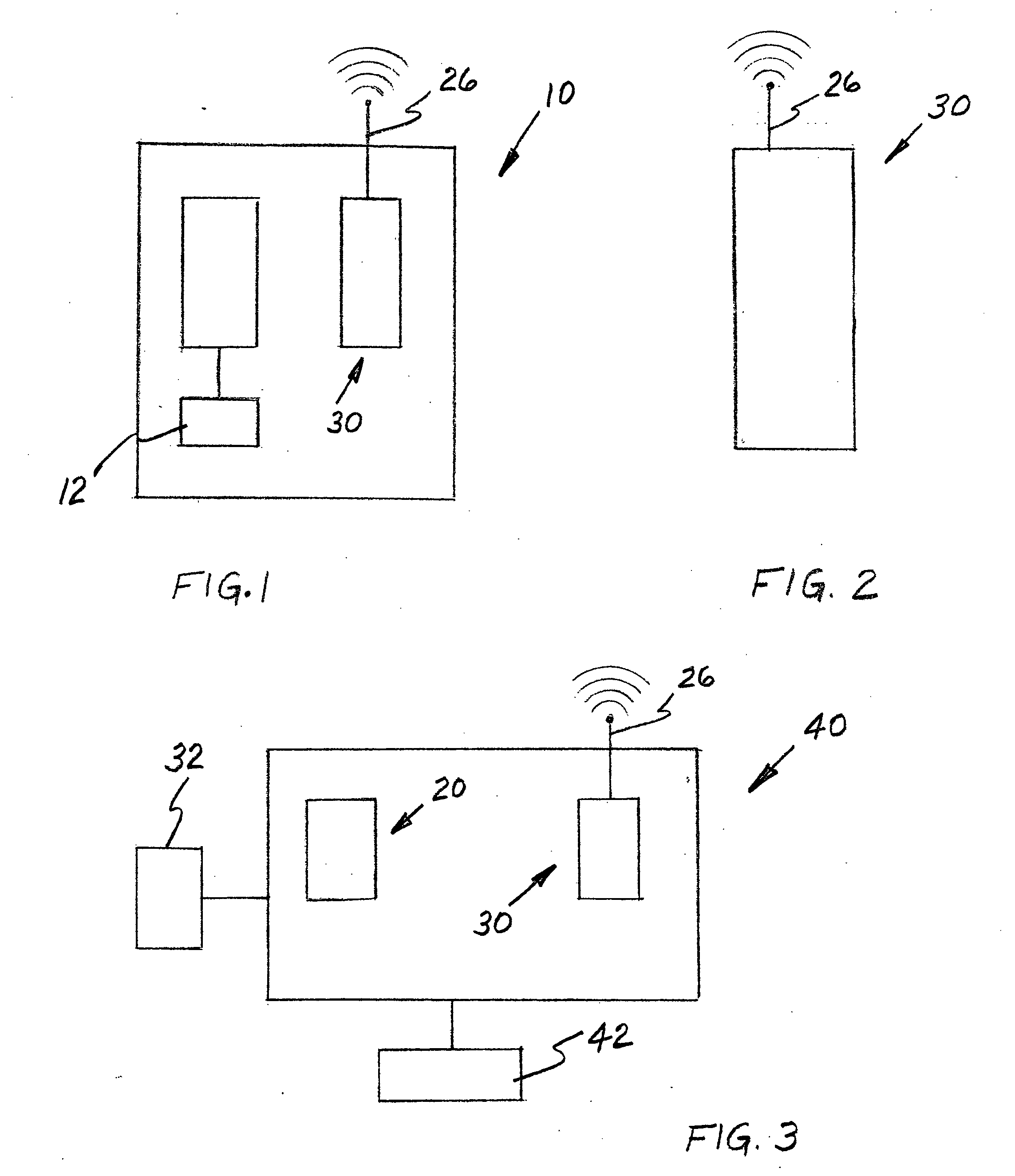
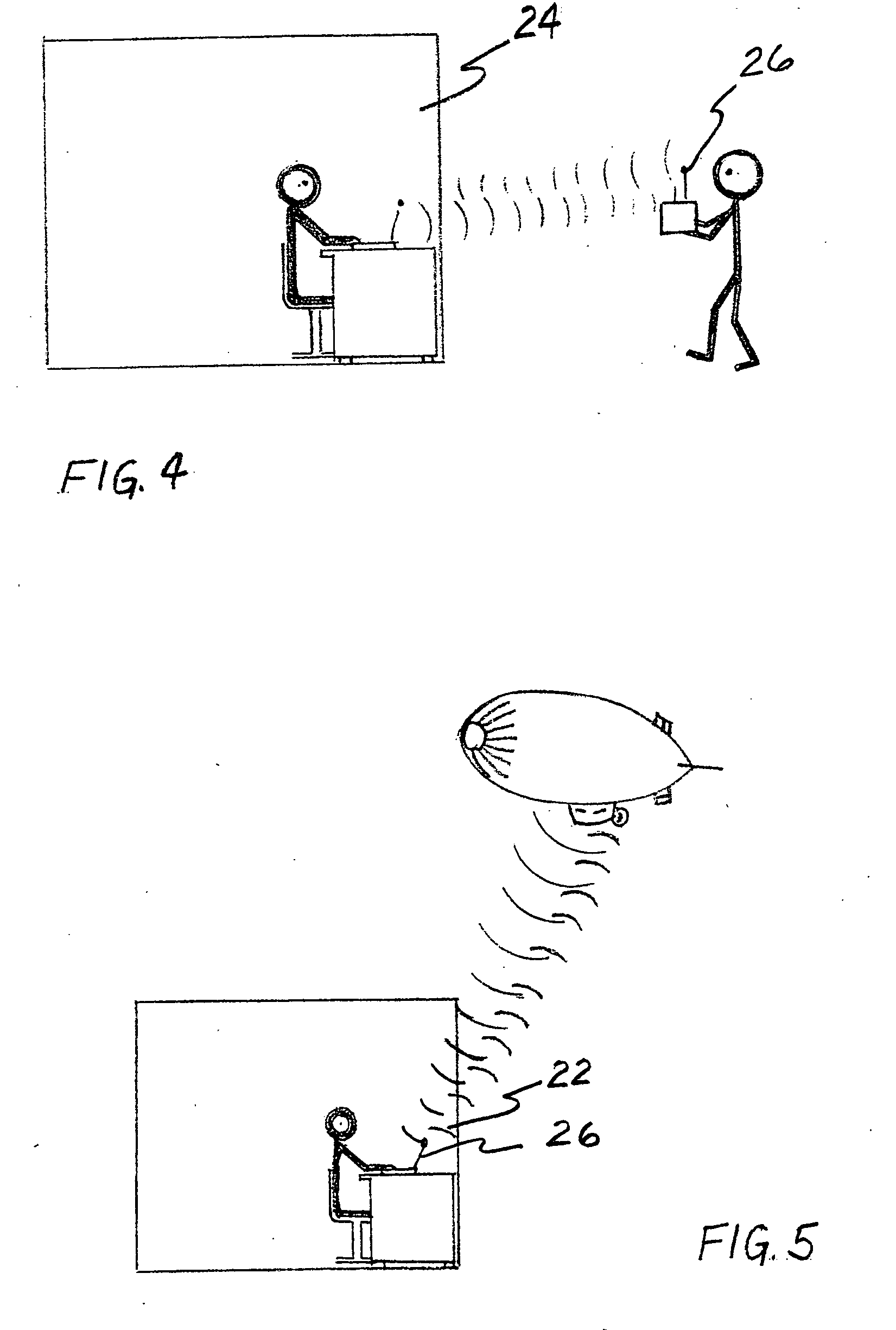
[0043] Now refer more particularly to FIGS. 1 and 2 of the drawings. Illustrated therein is an apparatus, generally designated 10, for measuring at least one of unintentional and intentional electromagnetic emissions for at least one of enabling electromagnetic location of predetermined electronic equipment giving off such at least one of unintentional and intentional electromagnetic emissions, tagging such predetermined electronic equipment and tracking such predetermined electronic equipment and various combination thereof. Apparatus 10 includes an emitter means 20 for providing an amplified electromagnetic energy which at least one of amplifies and changes a frequency content of the at least one...


PUM


Abstract

An apparatus for measuring at least one of unintentional and intentional electromagnetic emissions for at least one of enabling electromagnetic location of predetermined electronic equipment giving off such at least one of such unintentional and intentional electromagnetic emissions, tagging such predetermined electronic equipment and tracking such predetermined electronic equipment and various combination thereof. The apparatus comprises an emitter mechanism for providing an amplified electromagnetic energy which at least one of amplifies and changes a frequency content of the at least one of such unintentional and intentional electromagnetic emissions signature of a targeted electronic device by using an applied electromagnetic field generated by the emitter mechanism. There is a receiver for receiving the at least one of such unintentional and intentional electromagnetic emissions signature of such targeted electronic device.

Description

CROSS-REFERENCE TO RELATED APPLICATION [0001] This application is related to and claims priority from U.S. Provisional Patent Application titled “Enhanced Electromagnetic Remote Location of Electronic Equipment and Individuals who are Dependant on Electronic Equipment” filed on Oct. 18, 2004 and having Ser. No. 60 / 619,737.FIELD OF THE INVENTION [0002] The present invention relates, in general, to electronic devices and, more particularly, this invention relates to a method of and an apparatus for significantly enhancing the manner in which such electronic devices are located. BACKGROUND OF THE INVENTION [0003] As is well known in the prior art, electronic devices are an extremely important part of today's modern society for a number of reasons. They are used in industry to improve productivity, for example. They are also used by both industry and society, in general, as a means for communicating with one another, such as by cellular telephones and email. [0004] Unfortunately, as is ...

Claims


Application Information

Patent Timeline
IPC IPC(8): G01S13/06
CPCF41H3/00F41H13/0043G01S7/38G01S7/412
Inventor KELLER, WALTER J. III
Owner NOKOMIS
Why Eureka
Try Eureka