Covert surface relief hologram design, fabrication and optical reconstruction for security applications

a technology of optical reconstruction and hologram, applied in the field of storage of covert hologram data, can solve the problems of relatively low amount of information such magnetic stripes can store, hologram on the surface of a card can be somewhat easier to duplicate or alter, and the hologram disclosed in grot et al. is relatively inefficient, so as to achieve the effect of improving light efficiency

Inactive Publication Date: 2006-04-20
EURON CENT BANK
View PDF18 Cites 6 Cited by
  • Summary
  • Abstract
  • Description
  • Claims
  • Application Information

AI Technical Summary

Benefits of technology

[0015] Preferably, the reconstructed beam of a two-dimensional image is passed through an intervening optical system that is a spherical afocal telescopic system comprising a multiplicity of optical elements. Preferably, the intervening optical system is an afocal telescopic system comprising two spherical optical lens groups, positioned physically to bring the focal positions of the two spherical optical lens groups into coincidence. In one variation, a cylindrical imaging telescope is employed with an orthogonally-oriented single cylindrical lens for improved light efficiency. In one variation, a combination of cylindrical and spherical imaging optical elements is employed. Preferably, the holographic recording medium is a holographic material that records surface relief holograms. Preferably, the digital data is Written using modulation fringes which require reconstruction using tilted-plane imaging.

Problems solved by technology

However, security holograms used on credit cards are generally embossed only on the surface of the card, As such, while holograms in general are relatively difficult to duplicate, a hologram on the surface of a card can be somewhat easier to duplicate or alter.
That is, the hologram card disclosed in Grot et al. is relatively inefficient.
Additionally, while credit cards, and drivers licenses and identification cards, can typically store some information in a magnetic stripe often included with such cards, the amount of information such magnetic stripes can store can be relatively low.
As might be expected, unscrupulous dealers of counterfeit products attempt to replicate these holographic markers to make their products appear genuine.

Method used


Image

  • Covert surface relief hologram design, fabrication and optical reconstruction for security applications
  • Covert surface relief hologram design, fabrication and optical reconstruction for security applications
  • Covert surface relief hologram design, fabrication and optical reconstruction for security applications

Examples


second embodiment

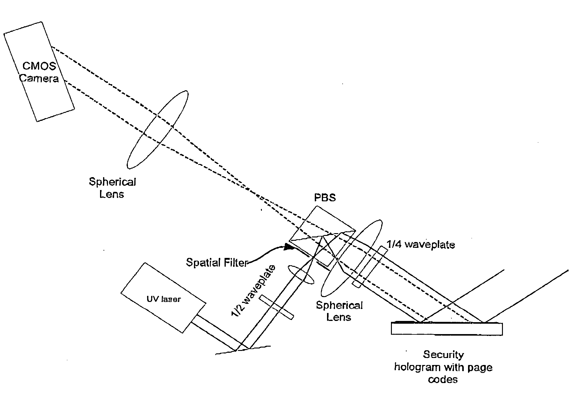
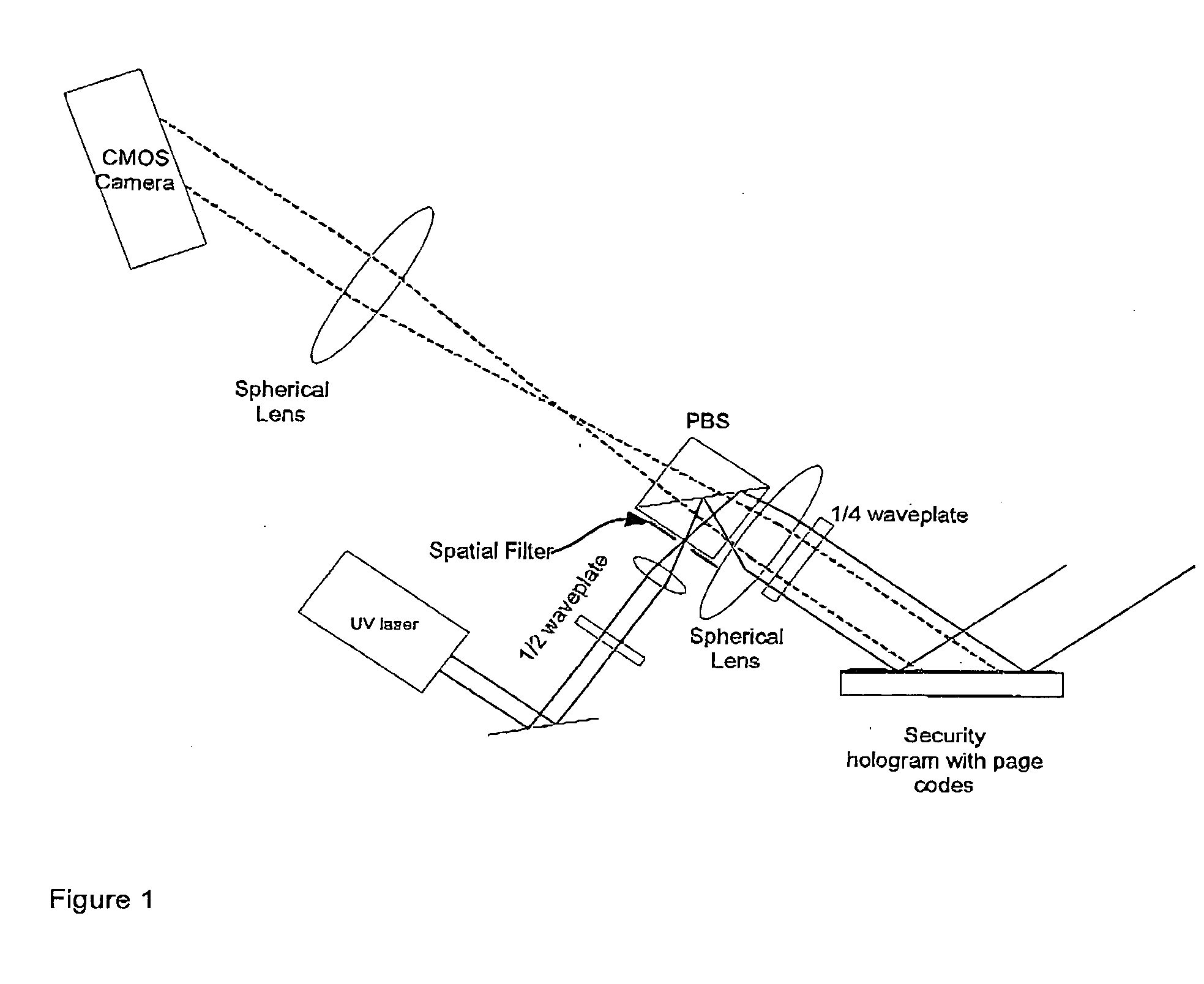
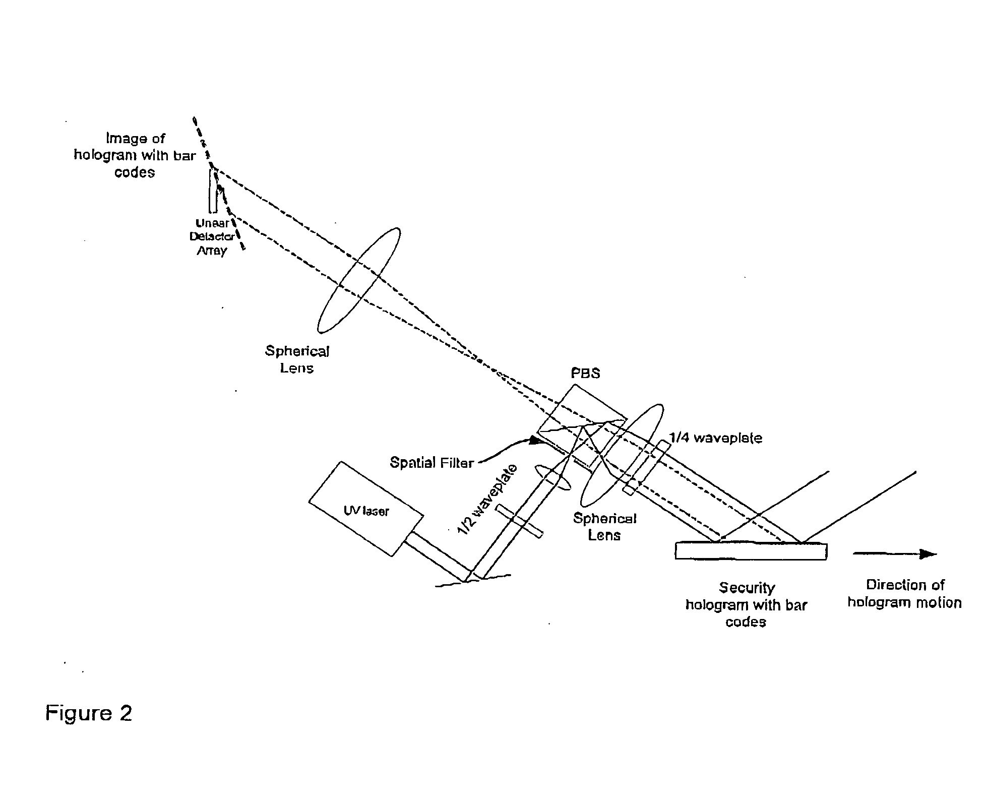
[0048] a tilted-plane reader system for invisible data holograms is shown in FIG. 2, which shows a reader system with spherical optics and a 1D linear output. Because of the one-dimensional line focus on the output detector array, this configuration does not have to be oriented as critically as the data page system in order to achieve focused operation upon reconstruction. The preferred embodiment for this reader system employs UV light to accomplish the readout of the hologram whose fringes have been designed to diffract only these wavelengths. In FIG. 2, the tilted image plane of the reconstructed data image is illustrated, and the linear detector will sample the bar codes as they move past. This approach requires continuous or stepped motion of the input hologram past the center of the illuminating beam. If magnification is desired for pixel-matching between the input and output planes, the telescope approach will be able to implement that requirement. This approach is not as lig...

third embodiment

[0049] a reader system for invisible data holograms is shown in FIG. 3, which shows a reader system with spherical and cylindrical optics and a 1D linear output. Because of the one-dimensional line focus illuminating the hologram and the one-dimensional line focus on the output detector array, this configuration does not have to be oriented as critically as the data page system in order to achieve focused operation upon reconstruction. The preferred embodiment for this reader system employs UV light to accomplish the readout of the hologram whose fringes have been designed to diffract only these wavelengths. This approach requires continuous or stepped motion of the input hologram past the center of the illuminating beam, and the output linear detector will sample the bar codes as they move through the illuminating beam. If magnification is desired for pixel-matching between the input and output planes, the telescope approach will be able to implement that requirement. This approach...


PUM


Abstract

Disclosed is an article having a surface-relief holographic recording medium having digital data that cannot be seen by human eye. Also disclosed is a tilted-plane optical reader system which can be used to read the stored data in the hologram.

Description

TECHNICAL FIELD [0001] The present invention relates to storage of data in holographic media. In particular, the present invention relates to storage of covert holographic data in an article having a holographic recording medium. BACKGROUND [0002] Holography is a familiar technology for displaying three dimensional images. Basically, two coherent light beams are caused to intersect in a holographic medium. An interference pattern or grating pattern results that is unique to the two beams and which is written into the medium. This grating pattern is referred to as the hologram and has the property that if it is illuminated by either of the beams used for recording, the illuminating beam diffracts in the direction of the second writing beam. To an observer, it appears as if the source of the second beam is still present at an observation plane. [0003] There are two significant types of holograms to consider: surface relief holograms and volume holograms. Surface relief holograms act o...

Claims


Application Information

Patent Timeline
Patent Type & Authority Applications(United States)
IPC IPC(8): G03H1/00
CPCG03H1/0011G03H1/0244G03H1/2286G03H1/26G03H2001/0016G03H2001/266G03H2001/303G03H2210/20G03H2222/15
Inventor WEAVER, SAMUEL P.MCLEOD, ROBERTCURTIS, KEVIN R.HILL, ADRIAN J.
Owner EURON CENT BANK
Why Eureka
Try Eureka