
Sliding bearing

a bearing and sliding technology, applied in the direction of shafts, bearings, rotary machine parts, etc., can solve the problems of insufficient fitting properties and degraded seizure resistance, and achieve the effect of fine roughness and excellent seizure resistan

Inactive Publication Date: 2006-04-20
TAIHO INDUSTRIES CO LTD
View PDF3 Cites 33 Cited by
  • Summary
  • Abstract
  • Description
  • Claims
  • Application Information

AI Technical Summary

Benefits of technology

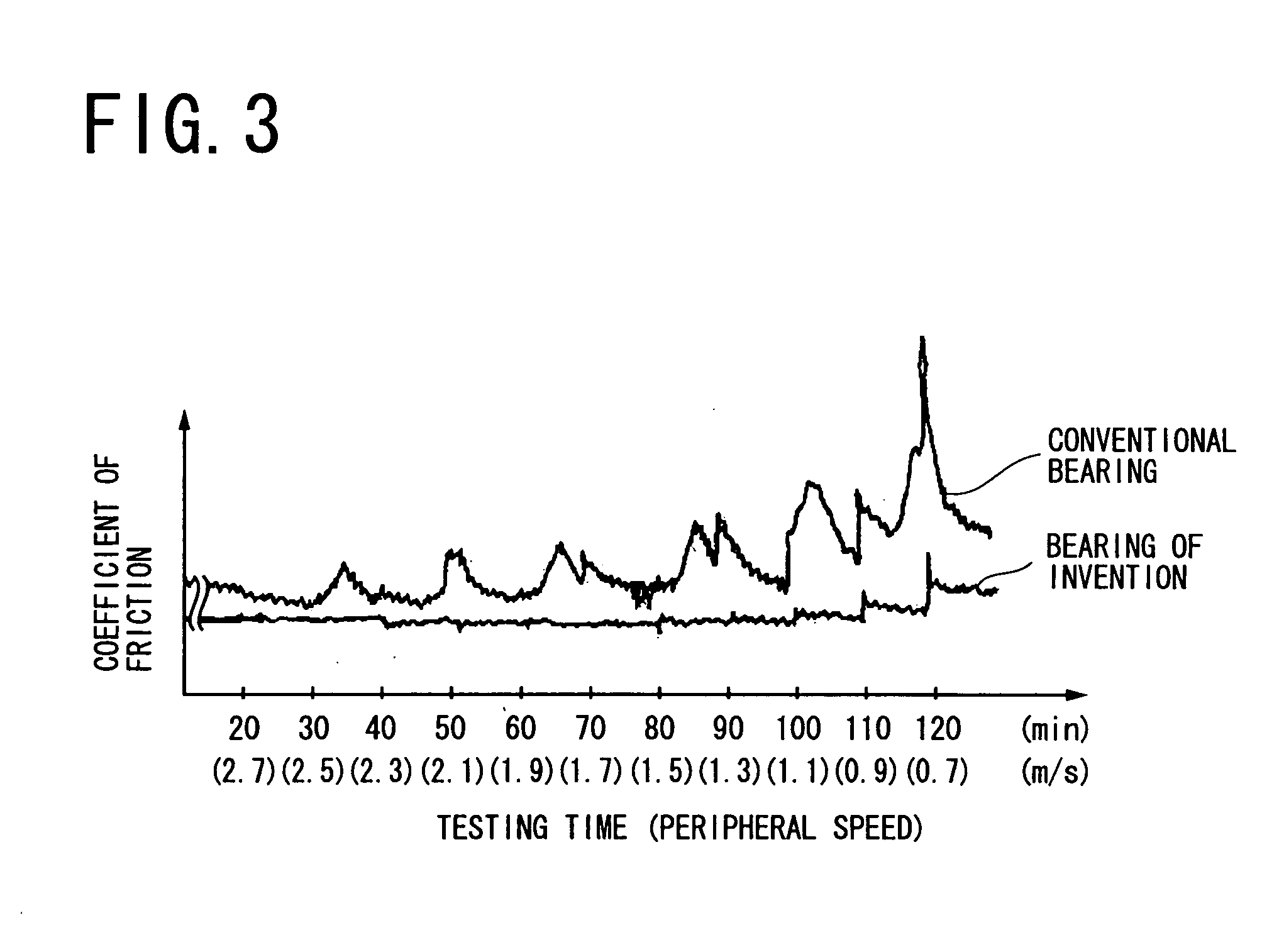
[0006] In view of the foregoing problems, the present invention provides a sliding bearing having an excellent seizure resistance and a fitting property response if a rotary shaft is subject to a high speed rotation.
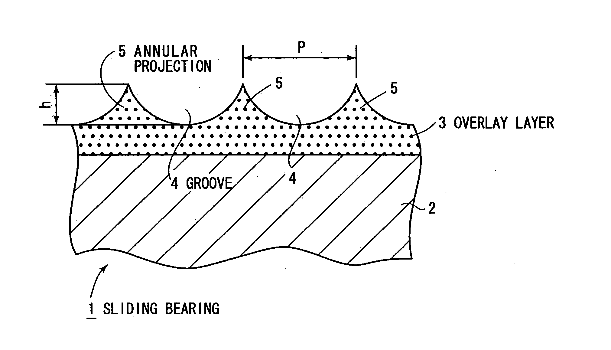
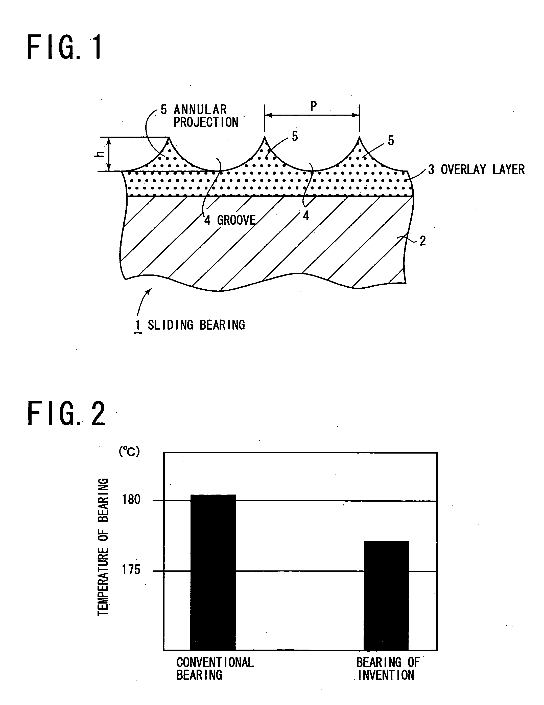
[0008] According to the present invention, a regular uneven configuration is formed on the surface of the overlay layer to secure a lubricant in the recesses of the uneven configuration to prevent the sliding bearing from assuming a high temperature, thus improving the seizure resistance. Since the bearing alloy layer has a surface at the boundary with the overlay layer which is machined to be a flat surface having a fine roughness, the overlay layer has a uniform cross-sectional configuration at all convex areas in the uneven configuration, whereby stresses applied from the rotary shaft to the individual convex areas are also uniform, allowing all of the convex areas to be subject to a uniform plastic deformation, thus improving the fitting property response of the sliding bearing.

Problems solved by technology

Consequently, when the rotary shaft is subject to a high speed rotation, the irregularly configured surface of the overlay layer cannot distribute a lubricant oil evenly, presenting problems that the seizure resistance may be degraded and / or a plastic deformation of the overlay layer resulting from the contact of the surface of the overlay layer with the rotary shaft may become uneven to result in an insufficient fitting property.

Method used


Image

  • Sliding bearing
  • Sliding bearing
  • Sliding bearing

Examples


Embodiment Construction

[0014] Several embodiments of the present invention shown in the drawings will now be described. FIG. 1 is an enlarged axial section of a cylindrical sliding bearing 1. The sliding bearing 1 comprises a metal backing layer, not shown, a bearing alloy layer 2 formed on the surface of the metal backing layer which is located toward the axis of the sliding bearing 1, and an overlay layer 3 formed on the surface of the bearing alloy layer 2.

[0015] The bearing alloy layer 2 is formed of an alloy which principally comprises a copper or an aluminium and has an inner peripheral surface which is machined to be a flat surface having a fine roughness and extending parallel to the axis of the sliding bearing 1. The overlay layer 3 comprises MoS2 as a solid lubricant and PAI resin as a binder resin. The overlay layer 3 is sprayed onto the surface of the bearing alloy layer 2 which is machined to be a flat form as by an air spray, and is set under heat, thus initially forming a layer on the orde...


PUM

PropertyMeasurementUnit
surface roughnessaaaaaaaaaa
thicknessaaaaaaaaaa
temperatureaaaaaaaaaa

Abstract

An overlay layer 3 comprising MoS2 as a solid lubricant and PAI resin as a binder resin is formed on a flattened surface of a bearing alloy layer 2, and a helical groove 4 and annular projections 5 are formed as an uneven configuration in and on the surface of the overlay layer. In accordance with the invention, a regular uneven configuration is formed on the surface of the overlay layer to allow a lubricant oil to be secured in recesses of the uneven configuration, allowing a seizure resistance to be improved. The bearing alloy layer is machined to have a flat surface having a fine roughness on its surface which represents a boundary with an overlay layer, whereby individual convex areas of the overlay layer are evenly subject to a plastic deformation, allowing the fitting property response of the sliding bearing to be improved.

Description

TECHNICAL FIELD [0001] The present invention relates to a sliding bearing, and more particularly, to a sliding bearing comprising a bearing alloy layer and an overlay layer disposed on the surface of the bearing alloy layer and formed by a solid lubricant and a resin. BACKGROUND ART [0002] A sliding bearing is known in the art which comprises an overlay layer disposed on the surface of a bearing alloy layer and formed by a solid lubricant and a resin, as disclosed in Japanese Patent No. 3133209 (hereafter referred to as patent literature 1) and Japanese Laid-Open Patent Application No. 2002-61652 (hereafter referred to as patent literature 2). [0003] In these patent literatures 1 and 2, the provision of the overlay layer improves the fitting property between the sliding bearing and a rotary shaft and a seizure resistance thereof by a plastic deformation of the overlay layer. [0004] However, in sliding bearings constructed according to the patent literatures 1 and 2, the surface of t...

Claims


Application Information

Patent Timeline
Patent Type & Authority Applications(United States)
IPC IPC(8): F16C33/02F16C33/12F16C33/10F16C33/20F16C33/24
CPCF16C33/201F16C2240/40F16C2202/54F16C33/1065F16C33/206F16C2208/42F16C2240/42F16C2240/60F16C2300/02
Inventor KAWAGOE, KIMIOHASHIZUME, KATSUYUKI
Owner TAIHO INDUSTRIES CO LTD
Learn More