Novel trachea cannula

A new type of endotracheal intubation technology, applied to endotracheal intubation, drug devices, other medical devices, etc., can solve the problems of damage to the camera device, the camera device falling into the trachea, harm, etc., to reduce the probability of friction and fall off, Improve reuse rate and avoid cross-contamination effect

Inactive Publication Date: 2016-04-13
THE AFFILIATED HOSPITAL OF QINGDAO UNIV
View PDF10 Cites 6 Cited by
  • Summary
  • Abstract
  • Description
  • Claims
  • Application Information

AI Technical Summary

Problems solved by technology

For example, when the endotracheal tube is inserted from the larynx, an external force is required to open the glottis. In the prior art, the bottom of the endotracheal tube is selected as an oblique cut surface. Although this solves the problem of opening the glottis, it cannot The problem of larynx injury on one side often occurs due to oblique insertion; when the endotracheal intubation is inserted into the corresponding position of the trachea, because the gap between the endotracheal intubation and the surrounding trachea needs to be closed, the usual endotracheal intubation is equipped with an air bag and an inflatable tube. , but the current setting of the airbag and the airbag inflatable connecting tube is relatively abrupt, which will increase the friction between the endotracheal tube and the inner wall of the respiratory tract during intubation, which will not only easily damage the inner wall of the respiratory tract, but also cause the airbag and the airbag inflatable connecting tube to shift or even fall off; In clinical practice, in order to clearly understand the state of tracheal insertion and the condition of the lesion, and then carry out corresponding emergency measures, although many products have realized the visual operation of intubation technology, in reality, after the endotracheal intubation is inserted, When it is necessary to insert other instruments and facilities into the endotracheal tube for foreign body suction or other operations, they often touch or even continuously hit the deep camera device, causing damage to or even scrapping the expensive camera device, and because of mucus or other foreign objects in the respiratory tract The adhesion of the camera device will often cause cross-infection of the camera device, and the camera device is not easy to be sterilized by high temperature or washing, making it difficult to reuse. What's more, the camera device may even fall into the trachea after being broken, causing more damage. Serious harm; and during the use of tracheal intubation, the patient is often in an unconscious state, and often bites the tracheal intubation with his teeth, but the material of the tracheal intubation is mostly silica gel, red rubber or PVC. , the tube body at the occlusal part will collapse or bend, or even rupture, affecting the normal ventilation of the patient; and among the existing products, the suction port and the surgical operation are the same entrance, which increases the difficulty of operation for medical staff

Method used


Image

  • Novel trachea cannula
  • Novel trachea cannula
  • Novel trachea cannula

Examples


Embodiment 1

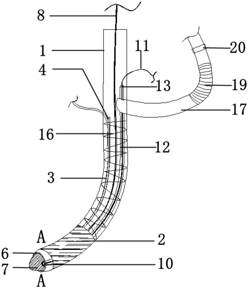
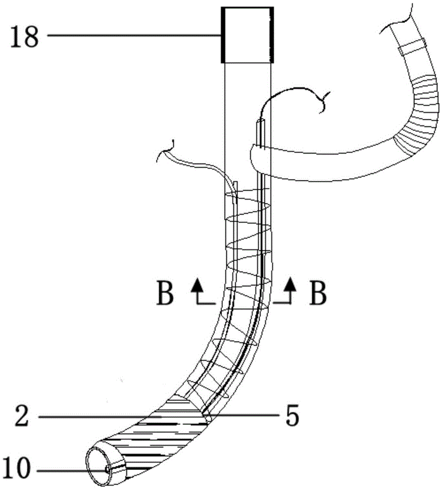
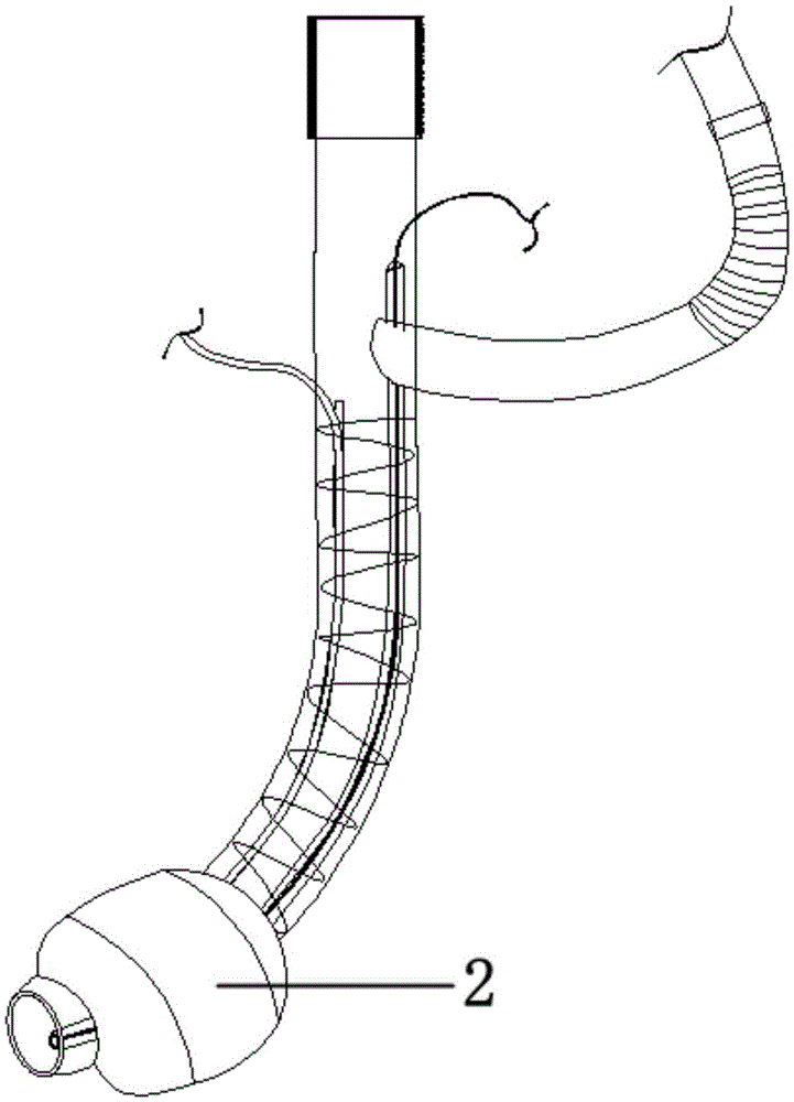
[0023] Such as Figure 1~3 As shown, a novel tracheal intubation tube includes a tube body 1, a balloon 2 and a balloon inflation connecting tube 3, the lower end of the balloon inflation connecting tube 3 communicates with the balloon 1, and the upper end of the balloon inflation connecting tube 3 connects with the balloon The inflatable device is connected, and a strip groove 4 is provided along the outer wall of the tube body 1, and the air bag inflation connecting pipe 3 is embedded in the strip groove 4; the lower section of the tube body 1 is provided with an annular groove 5, so that The airbag 2 is fixed in the annular groove 5 .

Embodiment 2

[0025] Such as figure 1 , 4 As shown in and 6, the difference from embodiment 1 is that the pipe body 1 has a certain inclination close-up at the extreme end, forming a flat circular section 6, therefore, the diameter of the circular section 6 is smaller than that of the pipe body The diameter of 1; the tube body 1 is also inserted with a tracheal intubation device, which includes a conical head 7 with a smooth blunt top and a push-pull rod 8 connected thereto, the conical head The bottom end of the part 7 is provided with a protruding clamping platform 9 , the diameter of the clamping platform 9 is larger than the diameter of the circular section 6 but smaller than the diameter of the pipe body 1 .

Embodiment 3

[0027] Such as figure 1 , 4 As shown in and 5, different from Embodiment 1, the novel tracheal intubation tube also includes a display device, a power supply, a camera 10 and a circuit 11 electrically connecting them to each other, and the camera includes an LED light and a camera; along the The inner wall of the tube body 1 is provided with a hemispherical convex tube 12, the bottom end of the convex tube 12 is closed, and the top end is provided with an opening 13 on the outer wall of the tube body, and the camera device 10 can be inserted into the said tube body from the opening 13. The bottom of the convex tube 12.


PUM


Abstract

The invention belongs to the field of medical equipment, and particularly relates to a novel trachea cannula. The novel trachea cannula comprises a cannula body, a balloon and a balloon inflation connecting pipe; the lower end of the balloon inflation connecting pipe is communicated with the balloon, the upper end of the balloon inflation connecting pipe is connected with a balloon inflation device, a strip-shaped groove is formed along the outer wall of the cannula body, and the balloon inflation connecting pipe is embedded in the strip-shaped groove; an annular groove is formed in the lower section of the cannula body, and the balloon is fixed in the annular groove. According to the novel trachea cannula, visual operation of the trachea cannula is achieved, and meanwhile it is guaranteed that a camera device is used repeatedly; insertion of the trachea cannula is safe, and the probability of disengagement of a gular cartilage and damage of the inner wall of a respiratory tract is reduced; collapse and bending of the trachea cannula body at the meshing part are prevented; oxygen supply is not interfered with surgical operation.

Description

technical field [0001] The invention belongs to the field of medical equipment, and in particular relates to a novel tracheal intubation tube. Background technique [0002] Endotracheal intubation refers to the technique of inserting a special endotracheal tube through the mouth or nose into the patient's trachea for anesthesia and rescue of the patient. It is also the most reliable means of keeping the upper airway open. The special catheter used in tracheal intubation is called endotracheal intubation, and endotracheal intubation is used as a breathing channel for patients to maintain life, and its safety is extremely important. [0003] At present, intubation technology is popular and mature clinically, but there are still some problems that endanger the life safety of patients. For example, when the endotracheal tube is inserted from the larynx, an external force is required to open the glottis. In the prior art, the bottom of the endotracheal tube is selected as an o...

Claims


Application Information

Patent Timeline
Patent Type & Authority Applications(China)
IPC IPC(8): A61M16/04
CPCA61M16/0402A61M16/0003A61M16/0461A61M16/0475A61M2210/0618A61M2210/0625
Inventor 孙健臧传善初春芹王培王艳婷
Owner THE AFFILIATED HOSPITAL OF QINGDAO UNIV
Why Eureka
Try Eureka