Integrated bias circuitry for ultrasound imaging devices

a bias circuit and ultrasound imaging technology, applied in the field of bias circuitry, can solve the problem that the cmut device is not currently used

Inactive Publication Date: 2006-04-20
SCI MED LIFE SYST
View PDF41 Cites 40 Cited by
  • Summary
  • Abstract
  • Description
  • Claims
  • Application Information

AI Technical Summary

Benefits of technology

[0007] The systems and methods described herein provide for an imaging system having bias circuitry for applying a bias voltage to one or more transducers. In one example embodiment, the imaging system includes an imaging device insertable into a living being and configured to image the interior of the living being. The imaging device includes an ultrasound transducer and bias circuitry electrically coupled with the transducer and configured to electrically bias the transducer. The imaging device can be coupled with a rotatable driveshaft and communicatively coupled with an image processing

Problems solved by technology

CMUT devices are not currently

Method used


Image

  • Integrated bias circuitry for ultrasound imaging devices
  • Integrated bias circuitry for ultrasound imaging devices
  • Integrated bias circuitry for ultrasound imaging devices

Examples


Embodiment Construction

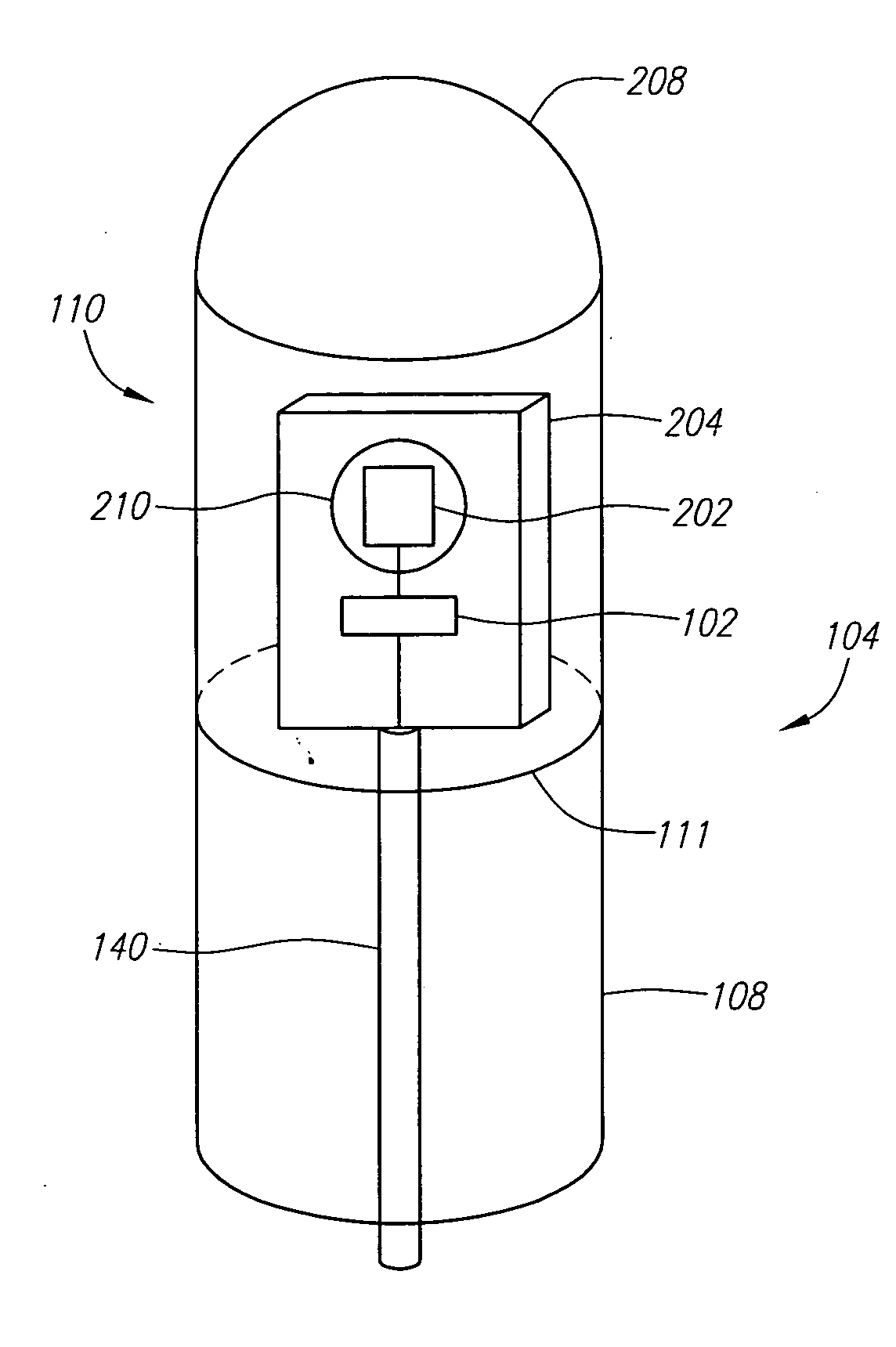
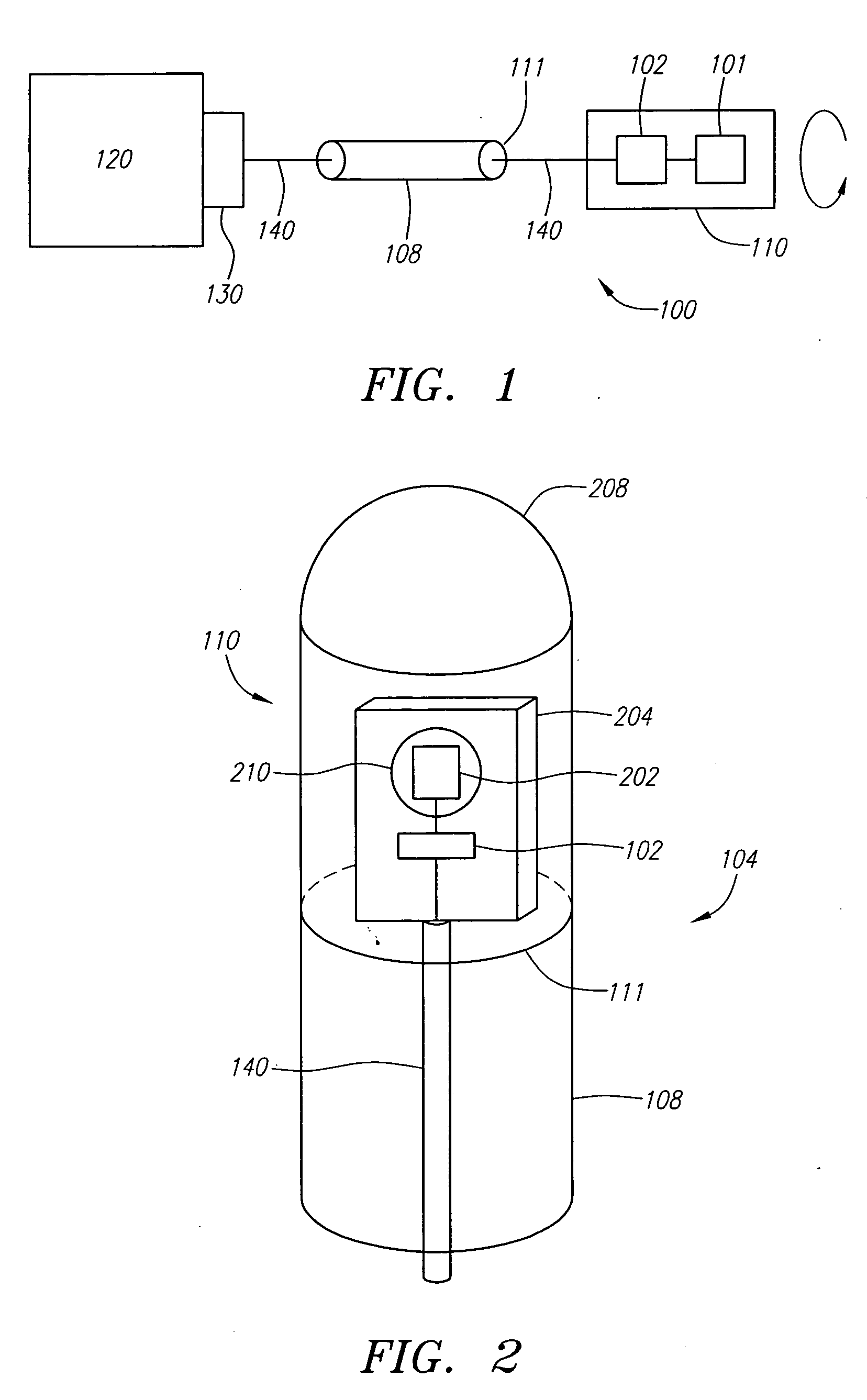
[0018] The systems and methods described herein allow the application of a bias voltage to one or more transducers implemented within an imaging system. FIG. 1 depicts one example embodiment of an imaging system 100 having bias circuitry 102. Preferably, the imaging system 100 is an IVUS imaging system. Here, an intravascular medical device 104, such as a catheter and the like, is communicatively coupled with an image processing system 106. Catheter 104 is preferably configured to image the interior of a living being, such as a body chamber or body lumen and the like. Catheter 104 preferably includes a rotatable driveshaft 108 with an imaging device 110 coupled thereto. In this embodiment, the imaging device 110 is mounted on the distal end 110 of the driveshaft 108. The catheter 104 also preferably includes an elongate outer sheath (not shown) having an inner lumen for slidably receiving the driveshaft 108 and imaging device 110.

[0019] To perform an imaging procedure of, for examp...


PUM


Abstract

The systems and methods described herein allow for the application of a bias voltage to one or more transducers implemented within a medical ultrasound imaging system. Bias circuitry is placed within an imaging device and used to apply a DC bias to one or more transducers requiring a DC bias to operate. The one or more transducers can be fabricated in a semiconductor manufacturing process and integrated with the bias circuitry on a common semiconductor substrate. Also provided is a method for operating the one or more transducers and bias circuitry using a communication channel having two signal lines.

Description

FIELD OF THE INVENTION [0001] The systems and methods relate generally to the use of bias circuitry for biasing an ultrasound imaging device in an intravascular ultrasound imaging system. BACKGROUND INFORMATION [0002] To generate an image using a medical ultrasound imaging system, such as an intravascular ultrasound (IVUS) or intracardiac echocardiography (ICE) imaging system, an ultrasound imaging device, typically including one or more transducers, is located on or within an intravascular device, such as a catheter and the like. The intravascular device is navigated into the body and the imaging device is used to image the desired body tissue. To do this, the transducer generates and transmits an ultrasound pulse into the body tissue. As this pulse strikes various layers of body tissue, echoes are reflected back to and received by the transducer. The transducer generates an electrical output signal representative of the strength of the received echo and outputs this signal to an i...

Claims


Application Information

Patent Timeline
IPC IPC(8): A61B8/14
CPCA61B8/12B06B1/0292G01S15/8906
Inventor KNIGHT, JON M.
Owner SCI MED LIFE SYST
Why Eureka
Try Eureka