Protective Engine Speed Control for a Centrifugal Clutch

a technology of centrifugal clutch and protection device, which is applied in the direction of electric control, speed sensing governor, machines/engines, etc., can solve the problems of limited heat development caused by slippage between the support of the centrifugal clutch and the clutch bell, and achieve safe separation between the output shaft and the combustion engine, safe clutch disengagement, and safe prevention of thermal overload of the clutch.

Active Publication Date: 2006-04-27
ANDREAS STIHL AG & CO KG
View PDF6 Cites 33 Cited by
  • Summary
  • Abstract
  • Description
  • Claims
  • Application Information

AI Technical Summary

Benefits of technology

[0005] In the engine speed range between the first engine speed (engaging speed) and the second engine speed (fully engaged speed), a protective control unit is activated that monitors the dwell time of the actual speed within the engine speed range. When the predetermined dwell time of the actual speed within the engine speed range is surpassed, intervention in the combustion process is effected, for example, by changing the ignition timing or the fuel supply, such that the engine speed is corrected to be outside of the engine speed range. In this way, the dwell time of the actual speed within the critical engine speed range between the first engine speed and the second engine speed is limited so that the possible heat development caused by slip between the support of the centrifugal clutch and the clutch bell is limited also. Thermal overload of the clutch can be safely prevented in this way.
[0006] As a further advantage, a safe separation between the output shaft and the combustion engine is achieved because a safe clutch disengagement during idling of the internal combustion engine is monitored and is thus ensured by means of the protective control unit according to the present invention.
[0009] The device comprises expediently a timing element for measuring the dwell time, in particular, a timing element that is a counter. Expediently, the revolutions of the crankshaft are added and, when a value that can be preselected is reached, intervention in the ignition control is carried out so as to lower the engine speed.

Problems solved by technology

In this way, the dwell time of the actual speed within the critical engine speed range between the first engine speed and the second engine speed is limited so that the possible heat development caused by slip between the support of the centrifugal clutch and the clutch bell is limited also.

Method used


Image

  • Protective Engine Speed Control for a Centrifugal Clutch
  • Protective Engine Speed Control for a Centrifugal Clutch

Examples


Embodiment Construction

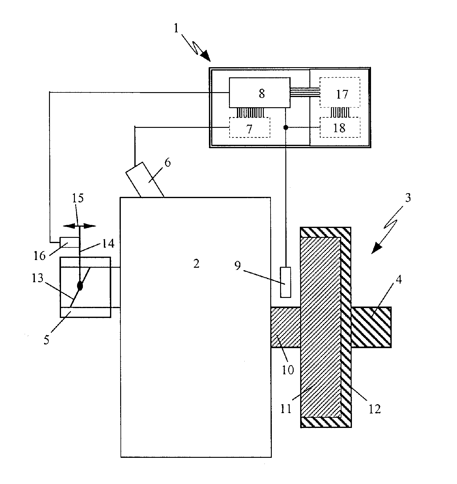
[0014] The control device 1 illustrated in FIG. 1 for controlling the engine speed of an internal combustion engine 2 is employed for an output shaft 4 that is operated by a centrifugal clutch 3. Such drives are used in motor chainsaws, cut-off devices, trimmers, blowers and similar portable, hand-held working tools (power tools). The internal combustion engine 2 is in particular a two-stroke engine.

[0015] The internal combustion engine 2—a single cylinder engine in the illustrated embodiment—takes in a fuel / air mixture through the carburetor 5. The mixture that flows into the combustion chamber (not illustrated) of the internal combustion engine 2 is compressed and then ignited by a spark plug 6 that is controlled by an ignition control unit 7. The ignition control unit 7 is monitored by a central processing unit (CPU) 8 that evaluates inter alia the speed signal of an engine speed sensor 9 and determines the position of the crankshaft 10 by means of the engine speed sensor 9. In ...


PUM


Abstract

A device that controls the engine speed of an internal combustion engine of a hand-held power tool has a protective control unit. The engine has an ignition control unit for controlling the ignition timing relative to a crank angle of a crankshaft based on the crankshaft speed and also has a centrifugal clutch driven by the crankshaft that begins to engage when a first engine speed is surpassed and is fully engaged when a second engine speed is reached. The protective control unit is activated within an engine speed range between the first and second engine speeds and monitors a dwell time of the actual engine speed within the engine speed range. When a predetermined dwell time of the actual engine speed is surpassed, the protective control unit intervenes in the combustion process and corrects the engine speed to a value that is outside of the engine speed range.

Description

BACKGROUND OF THE INVENTION [0001] The invention relates to a control device for controlling the engine speed of an internal combustion engine, in particular, of a two-stroke engine of a hand-held power tool such as a motor chainsaw, a cut-off device, a trimmer and the like. The internal combustion engine comprises an ignition control unit that controls the ignition timing of the spark plug relative to the crank angle of the crankshaft of the internal combustion engine as a function of the speed of the crankshaft. The engine further comprises a centrifugal clutch driven by the crankshaft that begins to engage when a first engine speed is surpassed and that is fully engaged when a second engine speed is reached. [0002] Portable, hand-held power tools, for example, motor chainsaws, cut-off devices, trimmers and the like, are usually driven by a two-stroke engine whose spark plug is connected to an ignition control unit that controls the ignition timing relative to the crank angle of t...

Claims


Application Information

Patent Timeline
Patent Type & Authority Applications(United States)
IPC IPC(8): F02D45/00
CPCF02D31/001F02D41/22Y10T477/79F02P5/1555Y02T10/46F02P5/1502F02D41/022F02D2400/06Y02T10/40
Inventor NICKEL, HANS
Owner ANDREAS STIHL AG & CO KG
Why Eureka
Try Eureka