Method of venting a spray metal mold

a technology of spray metal molds and vents, which is applied in the field of new venting methods of spray metal molding tools, can solve the problems of inability to replicate, inability to drill a multiplicity of small vent holes in the surface, and undesirable existing methods of producing mold surfaces with a plurality of vents, etc., and achieves the effect of minimal time and effective and economical methods

Active Publication Date: 2006-04-27
GENIUS SOLUTIONS ENG
View PDF20 Cites 4 Cited by
  • Summary
  • Abstract
  • Description
  • Claims
  • Application Information

AI Technical Summary

Benefits of technology

[0037] In method (ii), the channels are produced in the spray metal layer by holes placed in the model as in FIG. 9. In this method, the channels are holes produced in the spray metal layer as a result from the backpressure generated by the holes in the model. The hole in the model creates backpressure from the spray metal process and prevents spray material from being deposited in the area of the hole in the model. The depth of the hole in the model is typically deeper than the desired spray metal layer thickness. Hole size is typically from 0.003 to 0.080 inch in diameter and more preferably from 0.003 to 0.025 inch. In another configuration, the holes in the model can be connected to a gas supply to prevent spray metal buildup in the hole area as in FIG. 10.
[0039] In method (iv), the channels are produced by interconnected porosity in the spray metal layer. The interconnected porosity typically ranges from 5% to 35%. Porosity levels less than 5% in the spray metal layer typically prevent gas flow or venting in the spray metal layer.
[0041] The present invention described herein would be effective and economical in molding applications, wherein a venting surface is required to produce a part. The process described is superior to the other methods of venting a mold. The method described herein is inexpensive and requires minimal time. The present invention is unique compared to other methods in that this method is not limited by the size, material or surface texture. Furthermore, the spray metal mold requires only a few days to manufacture. The spray metal layer can be tailored to the tool applications environment, such as wear resistance or corrosion resistance by selecting a wide range of metals.

Problems solved by technology

The existing methods of producing a mold surface with a plurality of vents are undesirable for several reasons including time, cost and surface detail capability.
The disadvantages of the cast or the machined block mold in method (a) are the time and cost to drill a multiplicity of small vent holes in the surface.
The porous epoxy mold in (b) lacks mold face durability and the ability to replicate small surface features and surface texture.
The dilemma with the porous epoxy mold is that large media must be used to produce the porosity which reduces the strength of the mold.
If smaller media is used, the mold can be stronger but lacks enough interconnected porosity.
The porous sintered metal method in (c) is undesirable since the material is difficult to produce in bulk thicknesses, resulting in high material cost and long delivery times. The porous sintered material will further require machining or forming to the desired geometry.
Although time is the most noted drawback of electroforming, the mandrel or model requirements add additional cost and time to the electroformed mold.

Method used


Image

  • Method of venting a spray metal mold
  • Method of venting a spray metal mold
  • Method of venting a spray metal mold

Examples


Embodiment Construction

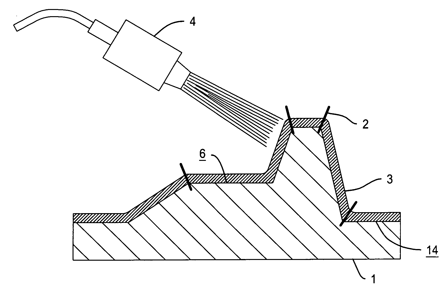
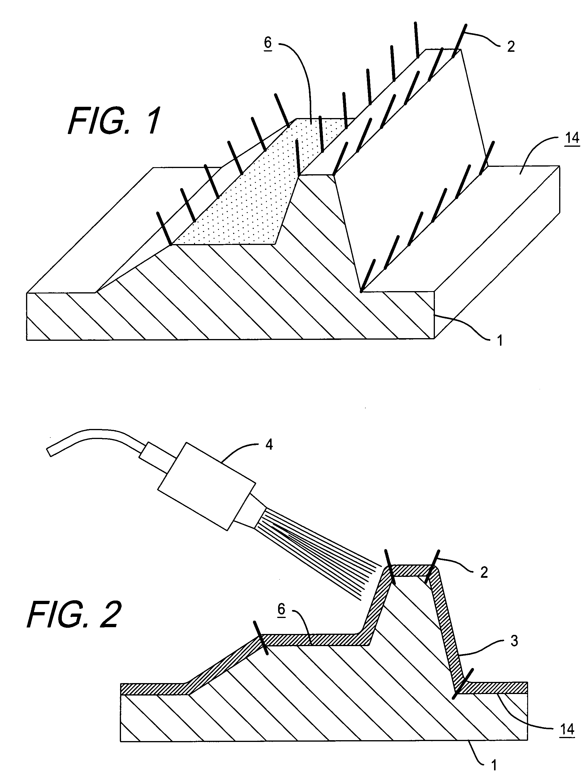
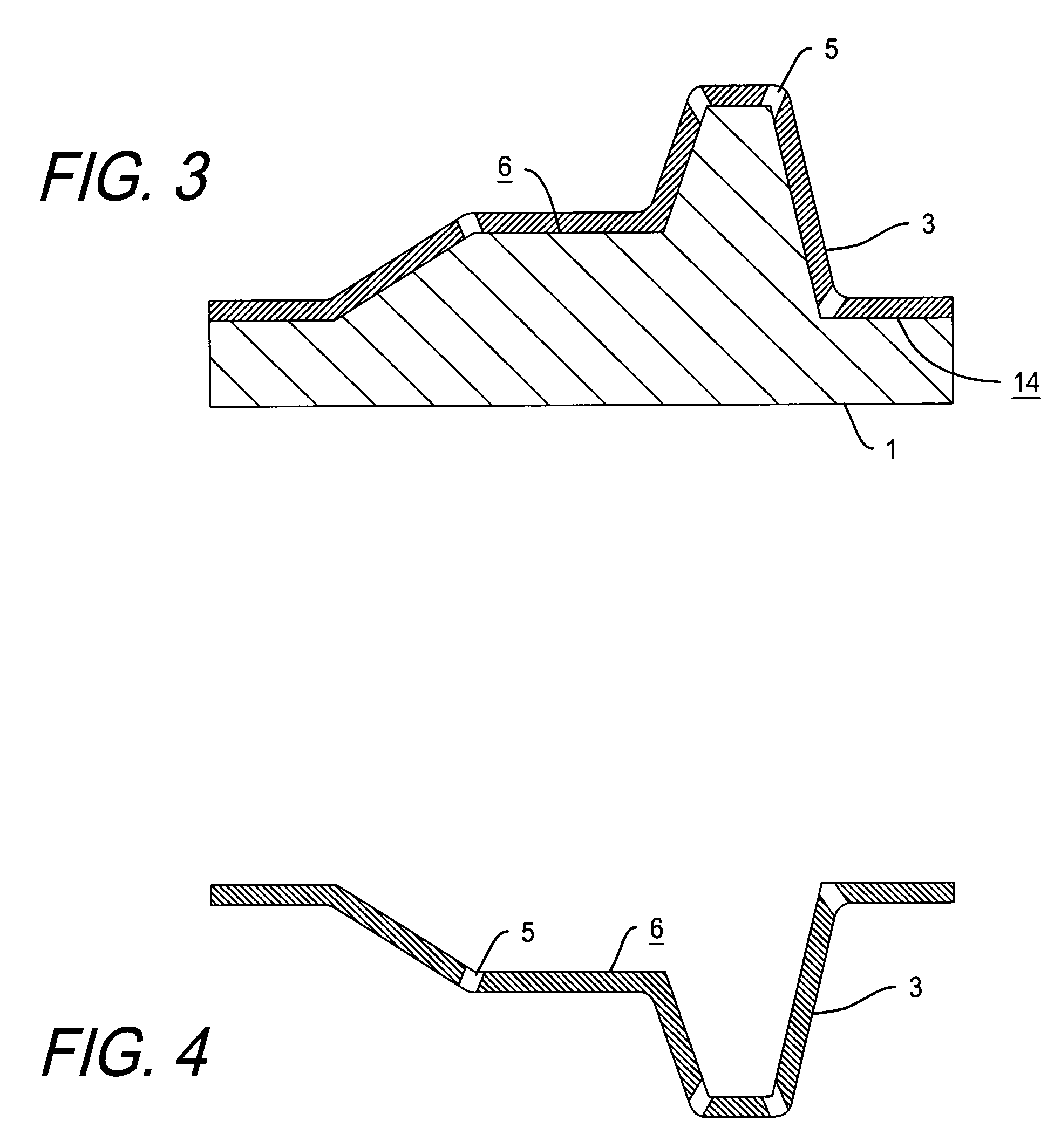
[0072] In the preferred embodiment, the process of producing a mold surface comprised of a layer of thermal spray metal providing venting channels through the thermal spray metal layer is described in FIG. 1 through FIG. 3 and FIG. 7 through FIG. 11. Further uses of the present invention and mold construction methods by way of example will be described in FIG. 4 through FIG. 6B.

[0073] Referring to FIG. 1, there is shown a pattern, target or mandrel, commonly referred to as a mold model (1), which is the inverse of the shape of the desired mold surface. The model is produced from a modeling board available from Huntsman of Salt Lake City, Utah and others. The surface is further grained in the required areas with the desired texture (6). A plurality of metal tapered pins with an outside diameter of 0.018 inch are inserted in the model surface about 0.13 inch deep or as deep as necessary to rigidly locate the pin in the model material. The pin is inserted at such an angle as to preven...


PUM

PropertyMeasurementUnit
porosityaaaaaaaaaa
porosityaaaaaaaaaa
thicknessaaaaaaaaaa

Abstract

The present invention relates to a novel method of venting a spray metal molding surface. More particularly the invention relates to a method of manufacturing a mold using a thermal spray process to produce a metal surface containing passages in the spray metal to vent fluid or gas from the forming surface. The present invention is primarily intended for mold tools, such as vacuum molds, injection molds or blow molds having vents or a multiplicity of holes in the forming surface to evacuate or supply gas in a mold.

Description

CROSS REFERENCE TO RELATED APPLICATIONS [0001] This application claims the benefit of U.S. Provisional Application No. 60 / 621,363 by Grigoriy Grinberg, filed Oct. 22, 2004.BACKGROUND OF THE INVENTION [0002] 1. Field of Invention [0003] The present invention relates to a novel method of venting a spray metal molding tool. More particularly the invention relates to a method of manufacturing a mold using a thermal spray process to produce a metal surface containing passages in the spray metal to vent or evacuate gas. [0004] 2. Description of Prior Art [0005] The present invention is primarily intended for mold tools, such as a vacuum mold having vents or a multiplicity of holes in the forming surface to evacuate or supply gas in a mold. By way of example, vacuum forming of heat-softened sheets of plastic material is well known. Molds suitable for such vacuum forming are typically porous or have holes in the forming surface. A vacuum is applied behind the forming surface that evacuates ...

Claims


Application Information

Patent Timeline
Patent Type & Authority Applications(United States)
IPC IPC(8): B22D23/00B22D29/00
CPCB22D17/145B22D17/22B22D23/003
Inventor GRINBERG, GRIGORIY
Owner GENIUS SOLUTIONS ENG
Why Eureka
Try Eureka