Gaseous fuel injector

a fuel injector and gaseous fuel technology, applied in the direction of machines/engines, combustion types, lighting and heating apparatus, etc., can solve the problems of sealing failure, cylinder direct injection engine may not be used long, and conventional combustion technology using liquid fossil fuel may not reach this requirement, etc., to achieve improved reliability, limited wear and bum, and improved ignition performance

Inactive Publication Date: 2006-04-27
DENSO CORP
View PDF4 Cites 46 Cited by
  • Summary
  • Abstract
  • Description
  • Claims
  • Application Information

AI Technical Summary

Benefits of technology

[0012] The present invention addresses the above disadvantages. Thus, it is an objective of the present invention to provide an injector that mainly injects a high-pressure gaseous fuel, has limited wear and bum-in, and has an improved reliability. It is also an objective of the present invention to provide an injector with an improved ignition performance in injecting the high-pressure gaseous fuel to realize a stable operation.

Problems solved by technology

However, conventional combustion technology using liquid fossil fuel may not reach this requirement.
A cylinder direct injection engine may not be used long in a case where a conventional gaseous fuel is used, because the conventional gaseous fuel has low lubricity.
Thus, there may be reliability disadvantages, such as wear and burn-in of a nozzle sliding portion of the injector, and sealing failure caused by the wear of a valve portion.
Also a compression ignition engine may have a disadvantage, such as an unstable operation with the gaseous fuels (e.g., the hydrogen gas and the natural gas, which have low cetane numbers).
Thus, misfire or deterioration of the operational performance is limited.
Thus, an effect of using the gaseous fuel may not be maximized.
S63-4365, the composition of the technique may be complex, because the seal oil, as well as the working fluid that drives the injector, is also supplied to the injector.
Moreover, the seal oil may continuously leak into the working fluid and the gaseous fuel, because a pressure of the seal oil is applied to a seal groove of the needle.
H1-88054, a lower portion of the needle is not lubricated sufficiently, because the working fluid does not easily reach a lower portion (or an injection hole side) of the seal oil storage due to pressure of the gaseous fuel, which is applied therein.

Method used


Image

  • Gaseous fuel injector
  • Gaseous fuel injector
  • Gaseous fuel injector

Examples


first embodiment

(First Embodiment)

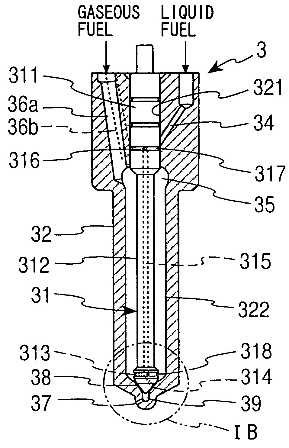
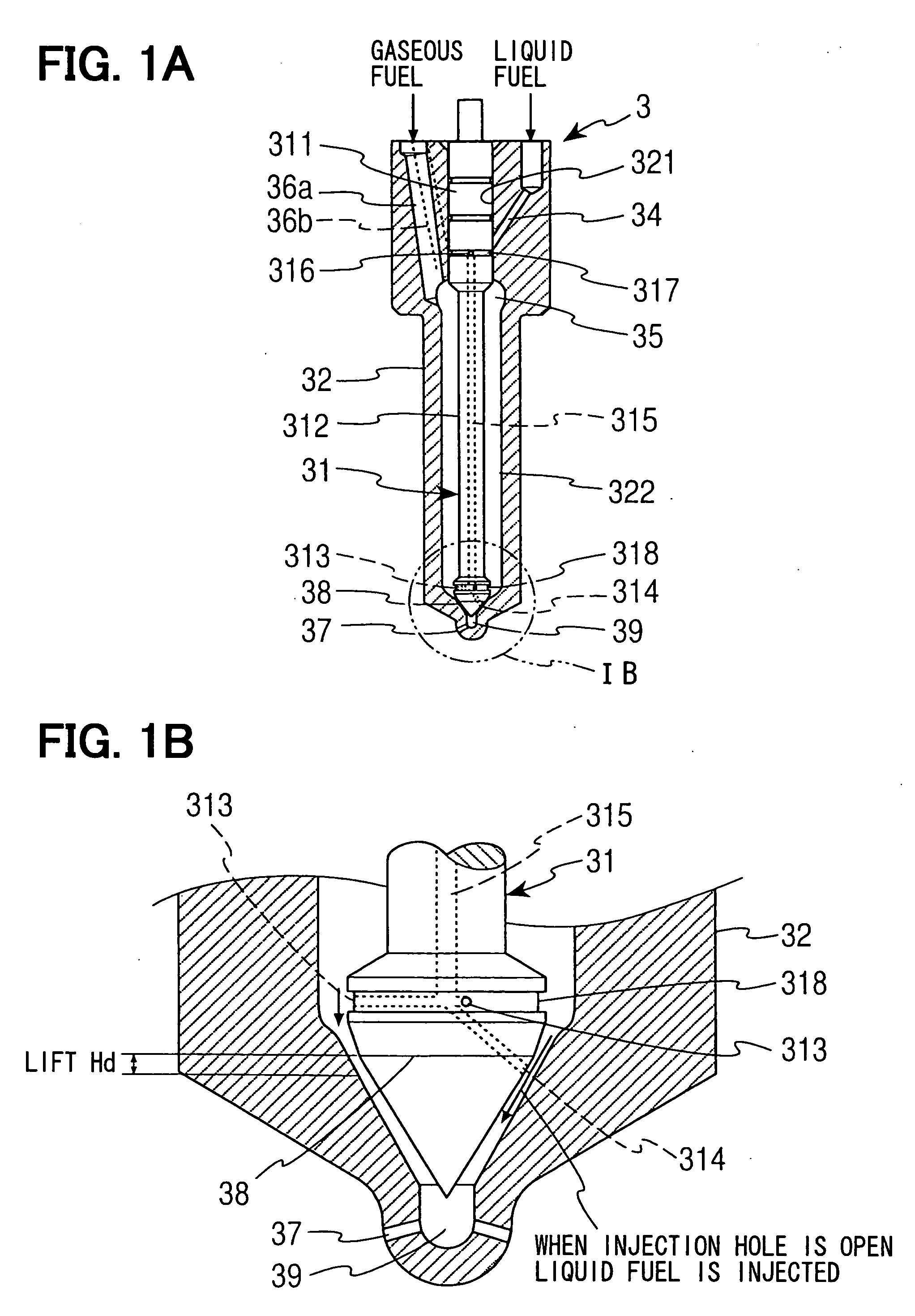
[0022] A first embodiment of a present invention will be described with reference to FIGS. 1A to 4. Injectors 1 according to the first embodiment, directly inject a high-pressure gaseous fuel to cylinders of the multi-cylinder compression ignition engine. Each combustion chamber of the cylinder has the corresponding injector 1.

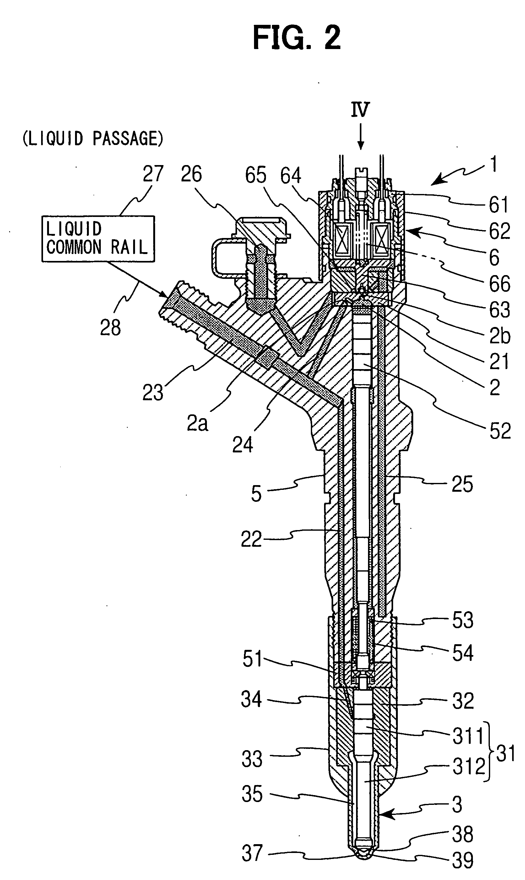
[0023]FIGS. 2 and 3 are longitudinal sectional views of the injector 1 according to the present embodiment. FIG. 1B is an enlarged view of a nozzle 3, which is a main part of the injector 1 according to the present embodiment. FIG. 2 describes a distribution passage of a working fluid, which is supplied to a control chamber 2 to drive the nozzle 3. FIG. 3 describes a supply passage of a high-pressure gaseous fuel, which is injected from the nozzle 3. A hydrogen fuel may serve as the high-pressure gaseous fuel. A liquid fuel, such as a light oil, serves as the working fuel. FIG. 4 is a plan view of the injector 1, which is a view from a direc...

second embodiment

(Second Embodiment)

[0050] A second embodiment will be described with reference to FIGS. 5 and 6. A present invention according to the second embodiment is different from the invention according to the first embodiment in the following points. The second high-pressure liquid passage 34 opens at the annular groove 317 when the needle 31 closes the injection holes 37 (or when the needle 31 is placed in a communication position). The seat lubrication liquid fuel supply hole 313 at the lower end portion of the needle 31 is located at immediately upstream of the seating part 38. The ignition facilitating liquid fuel supply hole 314 at the lower end portion of the needle 31 is located at immediately downstream of the seating part 38. Except for above-mentioned differences, a structure of a present embodiment is similar to that of the first embodiment. Similar components of a gaseous fuel injector 1 of the present embodiment, which are similar to the components of the injector 1 of the firs...


PUM


Abstract

The injector includes a nozzle, a needle, a control chamber, a working fluid supply passage, an electric switching valve, a high-pressure gaseous fuel supply passage and a lubrication liquid fuel supply passage. The nozzle has an injection hole, through which high-pressure gaseous fuel is injected. The needle is axially reciprocably received in the nozzle to open and close the injection hole. The needle includes a sliding portion and a valve portion. The control chamber applies a pressure to the needle. The working fluid supply passage supplies liquid fuel to the control chamber. The electric switching valve controls an inflow / outflow of the liquid fuel to / from the control chamber. The high-pressure gaseous fuel supply passage supplies the high-pressure gaseous fuel to the injection hole. The lubrication liquid fuel supply passage supplies the liquid fuel from the working fluid supply passage to the sliding portion and the valve portion.

Description

CROSS REFERENCE TO RELATED APPLICATION [0001] This application is based on and incorporates herein by reference Japanese Patent Applications No. 2004-309175, filed on Oct. 25, 2004. BACKGROUND OF THE INVENTION [0002] 1. Field of the Invention [0003] The present invention relates to a gaseous fuel injector, which directly injects a high-pressure gaseous fuel to cylinders of an internal combustion engine. [0004] 2. Description of Related Art [0005] In development of a next generation vehicle, a clean exhaust gas and a decrease of carbon dioxide are greatly required. However, conventional combustion technology using liquid fossil fuel may not reach this requirement. Development of a gaseous fuel engine using gas fossil fuels and hydrogen gas as alternative fuels for the liquid fossil fuel is progressing and some of the gaseous fuel engines are actually used. Here, the gas fossil fuels, which expectedly contribute effective combustion, include a natural gas and a petroleum gas. [0006] A...

Claims


Application Information

Patent Timeline
Patent Type & Authority Applications(United States)
IPC IPC(8): B05B7/12
CPCF02M43/04F02M61/042Y02T10/32Y02T10/36F02D19/0694F02M21/0263F02M21/0254F02D19/0647Y02T10/30
Inventor DATE, KENJIKATO, MASAAKI
Owner DENSO CORP
Why Eureka
Try Eureka