
Optical disk drive using one dimensional scanning

a technology of optical disk drive and scanning beam, which is applied in the direction of optical beam guiding means, head placement/mounting, instruments, etc., can solve the problems a two-dimensional beam steering mechanism is clearly more complex, and therefore inevitably more expensive, than a scanner, or beam steerer, and a two-dimensional lenslet array system. , the effect of occupying a larger volum

Inactive Publication Date: 2006-04-27
MMRI PHOTONICS
View PDF5 Cites 4 Cited by
  • Summary
  • Abstract
  • Description
  • Claims
  • Application Information

AI Technical Summary

Benefits of technology

[0007] Instead of moving a single lens across the entire usable part of the radius of the disk media, the entire usable part having the dimensions, the present invention provides a single line of N lenslets for a given media format that need be moved by a much smaller amount s / N, and that access data through the particular lenslet that happens to cover the desired location on the disk.

Problems solved by technology

The relatively large two-dimensional array is more cumbersome and costly than a one dimensional (1-D) lenslet array, and the two-dimensional beam steering mechanism is clearly more complex, and therefore inevitably more expensive, than a scanner, or beam steerer, that scans in one dimension only.
Furthermore, a system using a two dimensional lenslet array and scanning is likely to occupy a larger volume, which is undesirable in certain applications such as portable ‘notebook’ computers.
Such acceleration is clearly impractical in a compact, relatively inexpensive, reusable, device.

Method used


Image

  • Optical disk drive using one dimensional scanning
  • Optical disk drive using one dimensional scanning
  • Optical disk drive using one dimensional scanning

Examples


Embodiment Construction

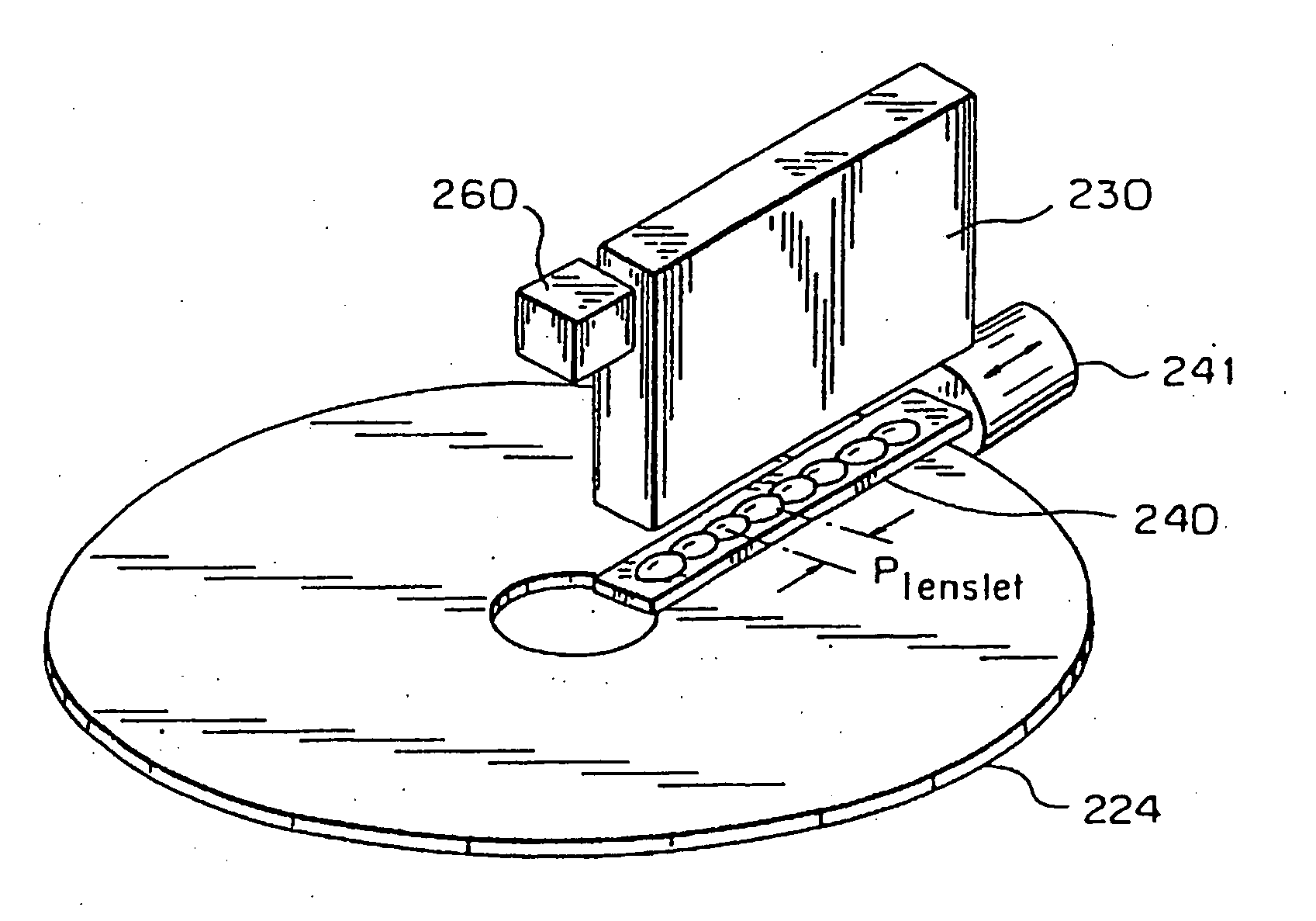
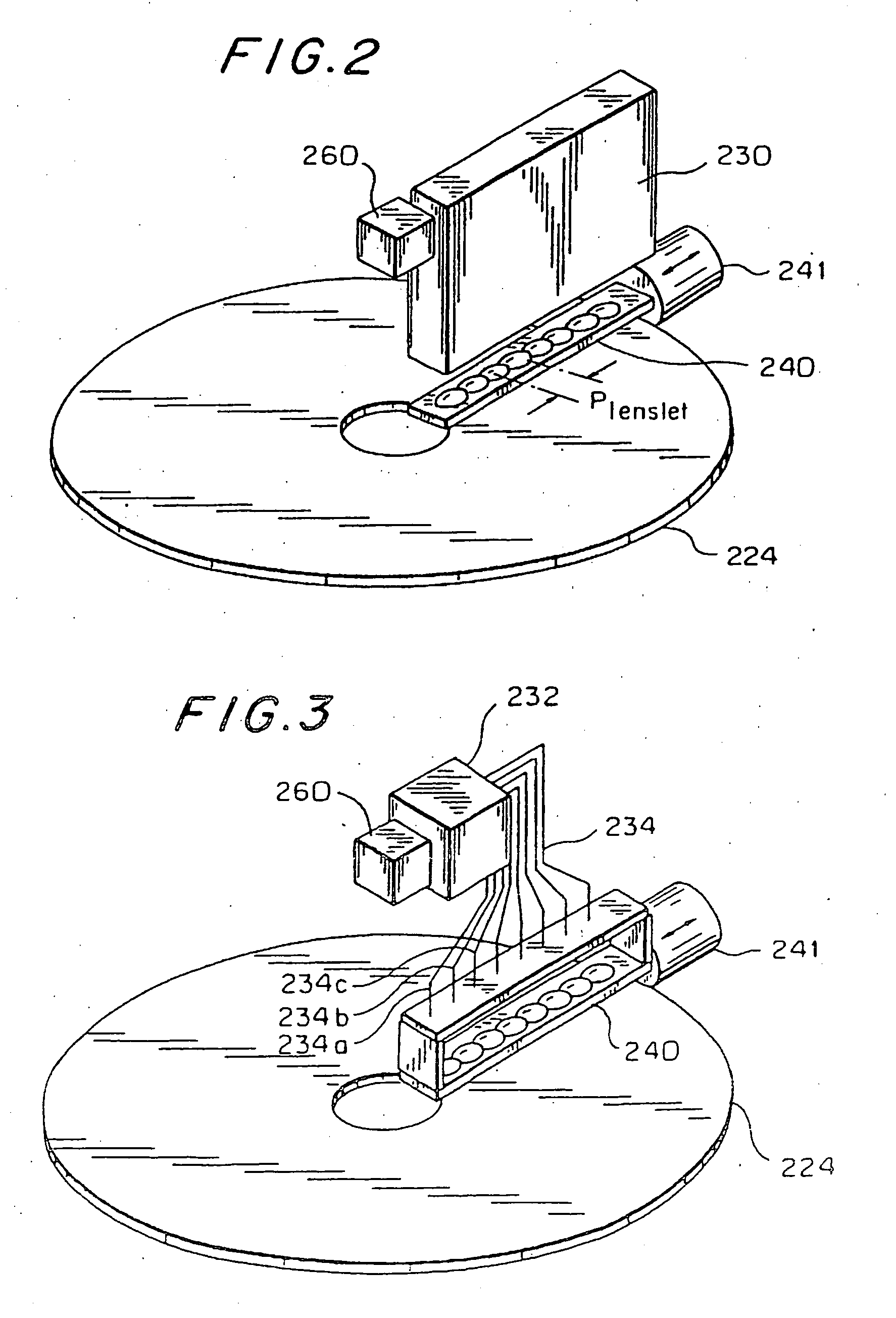
[0022] A basic simplified form of a disk drive according to the present invention is depicted in FIG. 2. A linear array 240 of lenslets is positioned above optical media 224. For reasons to be explained below, it may be desirable to provide more than a single linear lenslet array in some cases. Array 240 can be moved by an actuator 241 by a distance equal to, or slightly greater than, Plenslet≈s / N (see FIG. 2). Here, N is the number of the lenslets in the linear array and s is the usable portion of the disk radius, where: s=Douter-Dinner2

where Douter is the diameter of the outmost data track on the disk, and Dinner is the diameter of the innermost data track on the disk.

[0023] To access the proper location on disk 224, light from a source, typically a laser, in a subsystem 260 is directed by a beam steering, or light deflector, device 230 toward the selected lenslet of array 240. Device, or sub-system, 230 can be any suitable device that can direct a light beam in one of many pos...


PUM

PropertyMeasurementUnit
diameteraaaaaaaaaa
seek timeaaaaaaaaaa
massaaaaaaaaaa

Abstract

A system for optical scanning along one line with fast random access and high optical resolution, composed of: a plurality of first lenslets (240) constructed for use with a selected media format (224), the plurality of lenslets (240) all being disposed in a single row and being spaced apart by a given center-to-center distance; a movable mount carrying the plurality of lenslets (240), a linear motion actuator (241) coupled to the mount for moving the mount in a direction substantially parallel to the single row over a distance having a maximum value that is substantially equal to or slightly greater than the given center-to-center distance; at least one light source (260); a light directing unit (234) for directing light from the source to any one or two selected lenslets (240); and a control unit for controlling the light directing unit (234).

Description

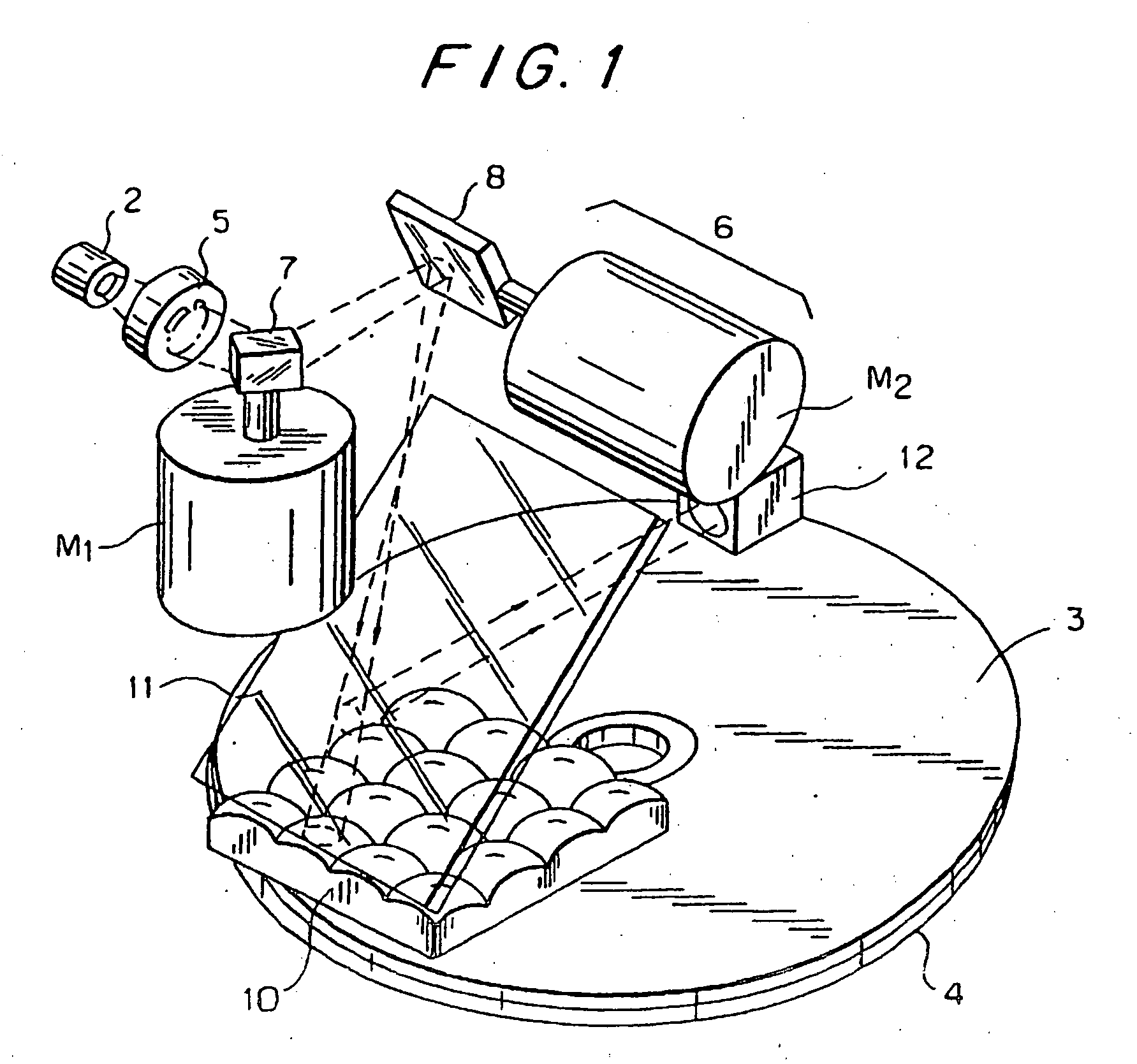
CROSS-REFERENCE TO RELATED APPLICATION [0001] This application relates to subject matter disclosed in U.S. application Ser. No. 09 / 984,369, filed Oct. 30, 2001, the entire disclosure of which is incorporated herein by reference.BACKGROUND OF THE INVENTION [0002] Optical disk drives that utilize a combination of a scanner (or scanners or beam steering device or devices) and a lenslet-array were described in Refs. [1], [2] and [3]. The disclosures, including the terminology, generalizations, and conventions used in Refs. [1] and [2], as well as works cited therein, are incorporated herein by reference. [0003] In most of the embodiments described in references [1] through [3], there is a stationary two dimensional (2-D) lenslet array, and some means for two dimensional beam steering (or scanning), in order to facilitate addressing each lenslet in the two dimensional array individually (see, for example, FIG. 1, which is taken from ref. [1]). The relatively large two-dimensional array i...

Claims


Application Information

Patent Timeline
Patent Type & Authority Applications(United States)
IPC IPC(8): G11B7/00G11B7/09G11BG11B7/135G11B7/14
CPCG11B7/08547G11B7/14G11B7/1374
Inventor ASSIS, TSURIELGLASER, RANNGLASER-INBARI, ISAIA
Owner MMRI PHOTONICS
Learn More