Enclosed container lid opening/closing system and enclosed container lid opening/closing method

a container lid and closed container technology, applied in the field of front-opening interfaces, can solve the problems of inability to pass through a gas having a sufficient flow rate, inability to achieve the desired wafer processing normally performed by passing through the subsequent processing chamber in some cases, and difficulty in sufficiently removing contaminants or the like by a conventional method, so as to achieve the effect of removing contaminants

Active Publication Date: 2006-04-27
TDK CORPARATION +1
View PDF26 Cites 40 Cited by
  • Summary
  • Abstract
  • Description
  • Claims
  • Application Information

AI Technical Summary

Benefits of technology

[0016] The present invention has been made in view of the above-mentioned circumstances. An object of the present invention is to provide a storage container lid opening / closing system such as a FIMS having an apparatus capable of effectively removing contaminants or the like which are deposited on a wafer for purging an inner portion of a front-opening type object-to-be-stored storing container such as a FOUP. Another object of the present invention is to provide a method of purging such a storage container.

Problems solved by technology

When the wafers on which the contaminants or the like are deposited are taken in a subsequent processing chamber, desirable wafer processing which is normally performed by passing through the subsequent processing chamber is impossible in some cases.
Therefore, it may be difficult to pass a gas having a sufficient flow rate through spaces above and below each of the wafers held at minute intervals.
The contaminants or the like are deposited mainly on an upper surface of each of the wafers or a lower surface thereof, so it may be difficult to sufficiently remove the contaminants or the like by a conventional method.
However, it may be also difficult to perform effective replacement on gases or the like which are present between adjacent wafers held with a minute space.
Therefore, it may be similarly difficult to obtain an effect in which the contaminants deposited on the upper and lower surfaces of each of the wafers are removed.
However, it may be difficult to provide a gas introducing flow path having a large inner diameter in view of an actual structure.
Therefore, there is a problem in that the system disclosed in JP 2003-045933 A or the pod disclosed in JP 11-251422 A, which requires a structure different from that of this standard cannot be commonly applied to the support base and the like which are currently normally used.

Method used


Image

  • Enclosed container lid opening/closing system and enclosed container lid opening/closing method
  • Enclosed container lid opening/closing system and enclosed container lid opening/closing method
  • Enclosed container lid opening/closing system and enclosed container lid opening/closing method

Examples


Embodiment Construction

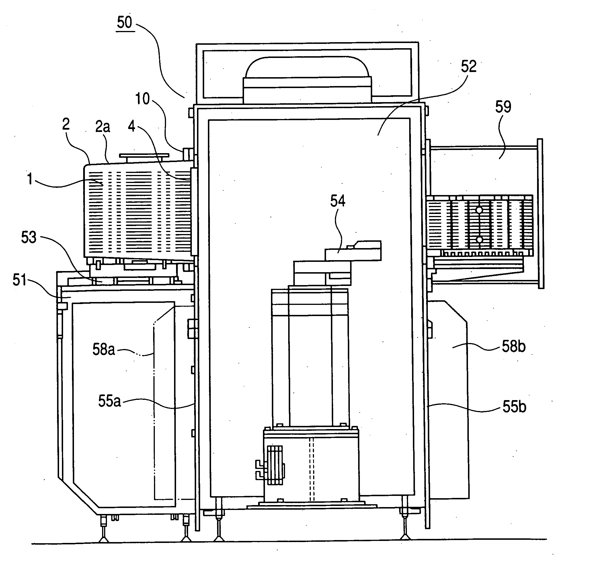
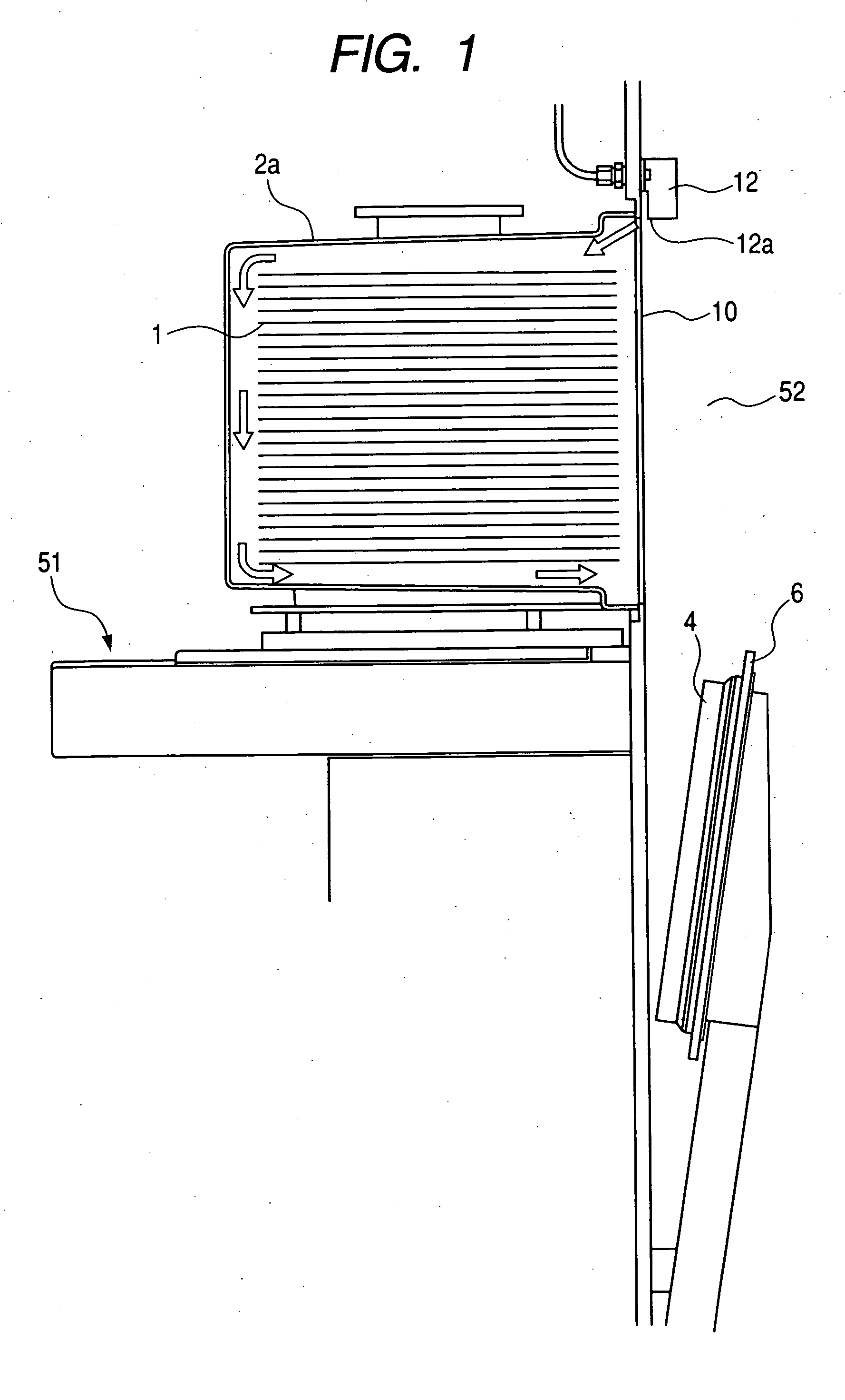
[0035] Hereinafter, embodiments of the present invention will be described with reference to the drawings. FIG. 1 is a schematic structural view showing a main part of a FIMS system including a purge apparatus according to an embodiment of the present invention, which shows a state when a cross section of the main part of the FIMS system holding a pod which is opened with a pod lid is viewed from side. Note that the pod inherently includes various members such as a rack for supporting wafers and a seal member located between the pod lid and the pod. Further, various members are attached to a door. However, these members are not directly associated with the present invention, so the detailed illustration and description will be omitted.

[0036] In FIG. 1, a main body 2a of a pod 2 includes a space for storing wafers 1, each of which is an object to be processed, in an inner portion thereof. The main body 2a has a box shape and includes an opening portion provided in one of surfaces lo...


PUM

PropertyMeasurementUnit
angleaaaaaaaaaa
sizeaaaaaaaaaa
distanceaaaaaaaaaa

Abstract

In order to easily and surely remove contaminants or the like from wafers stored in a pod (FOUP), a gas supply pipe is located above an opening portion in a FIMS system. A clean gas is blown to the upper surfaces of the wafers stored in the inner portion of the pod through the gas supply pipe to remove the contaminants or the like from wafers.

Description

BACKGROUND OF THE INVENTION [0001] 1. Field of the Invention [0002] The present invention relates to a so-called front-opening interface mechanical standard (FIMS) system used when wafers held in a transfer container which is called a pod are transferred among semiconductor processing apparatuses in a semiconductor manufacture process or the like. More specifically, the present invention relates to a purging apparatus and a purging method for cleaning the inner portion of a pod in the FIMS system in which the pod containing the wafers which is called a front-opening unified pod (FOUP) is placed and the wafers are moved from and into the pod. [0003] 2. Related Background Art [0004] Up to now, a semiconductor manufacture process has been conducted in a so-called clean room in which a room in which semiconductor wafers are treated has high cleanliness. However, in order to deal with the increase of a wafer size and the reduction of a cost required to maintain the room clean, a method o...

Claims


Application Information

Patent Timeline
Patent Type & Authority Applications(United States)
IPC IPC(8): B65H1/00B65B69/00B65G1/00H01L21/677
CPCH01L21/67017H01L21/67772H01L21/68
Inventor MIYAJIMA, TOSHIHIKOSUZUKI, HITOSHIIGARASHI, HIROSHI
Owner TDK CORPARATION
Why Eureka
Try Eureka