
Power boat drive system with multiple gearboxes

Inactive Publication Date: 2006-04-27
SUPERIOR GEAR BOX CO
View PDF23 Cites 23 Cited by
  • Summary
  • Abstract
  • Description
  • Claims
  • Application Information

AI Technical Summary

Benefits of technology

[0004] This invention provides a drive system for a power boat powered by a single engine having a primary gearbox and opposed, outboard gearboxes, all gearboxes, being cooled by the cooling pads connected to the gearboxes. A cushioned cradle drive support system facilitates the placement of the engine and the drive system.
[0006] This three gear, split shaft balanced arrangement increases the torque capacity of the propeller shafts measurably and to almost twice that of a continuous lateral drive shaft. In the embodiment shown a marine transmission is provided between each outboard gearbox and its associated gear propeller shaft and the direction of rotation of the propeller depends on the direction required by the marine transmission.
[0009] This modified arrangement can be used with much narrow power boats, for example with boats having twin drive propellers as close as thirty-four inches as opposed to fifty-four inches with the power boat drive system described in the previous embodiment. There are other advantages. For example, dispensing with one gearbox and its lateral drive shaft saves considerable weight, up to one hundred pounds, resulting in a savings in cost of approximately one-third over the system previously described. And this advantage is achieved with relatively small power loss.
[0012] While the length of the engine room is increased, and the engine must be mounted off-center, this can be compensated for by counterbalancing or by moving the center of gravity of the drive system closer to the centerline of the boat. Shaft alignment may also become more critical as the transverse shaft length is increased but this disadvantage is more than compensated for by the advantages set forth above.

Problems solved by technology

Such boats have not been particularly successfully owing partly to the inadequate cooling of the drive gears and complicated mounts for the drive system.

Method used


Image

  • Power boat drive system with multiple gearboxes
  • Power boat drive system with multiple gearboxes
  • Power boat drive system with multiple gearboxes

Examples


Embodiment Construction

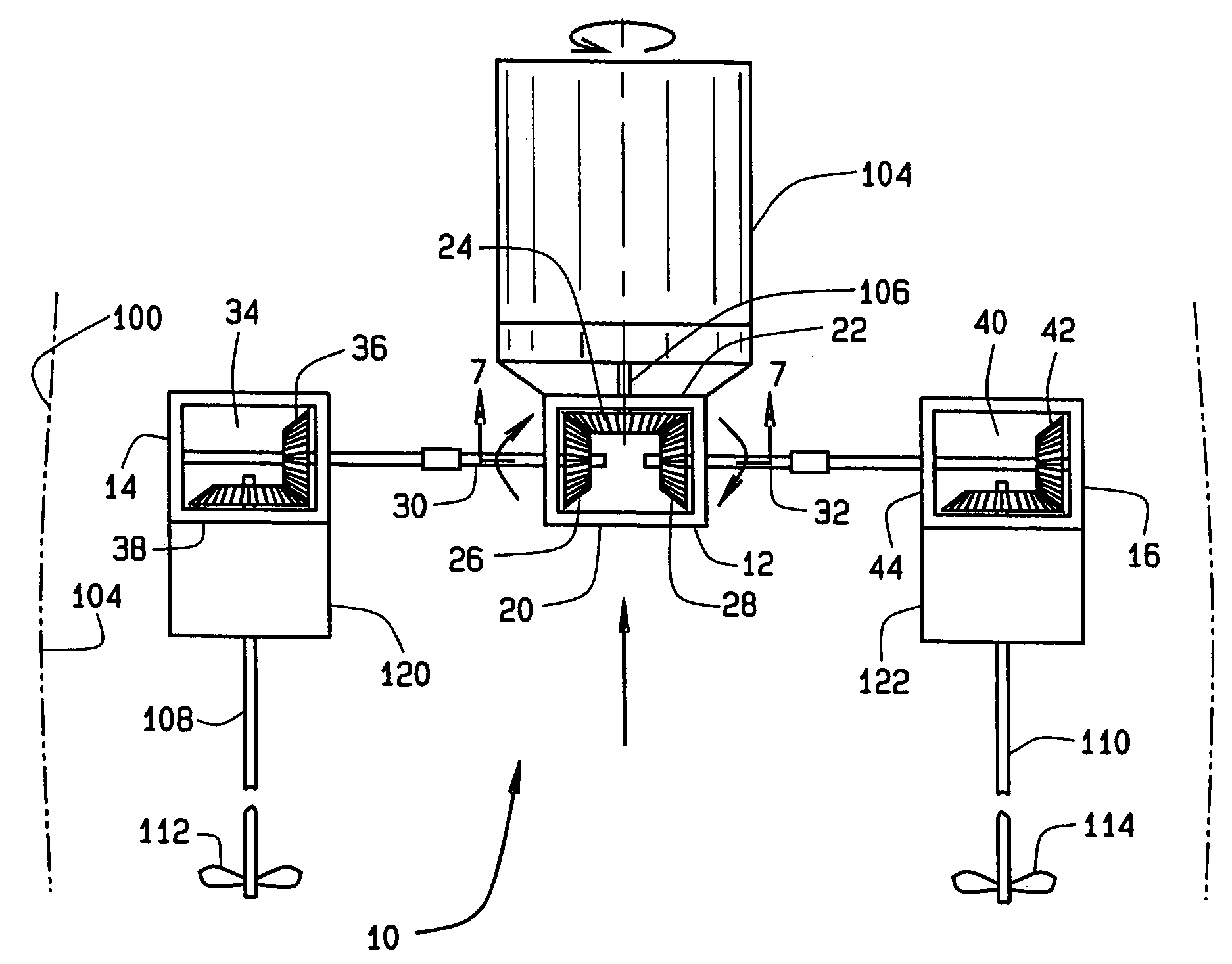
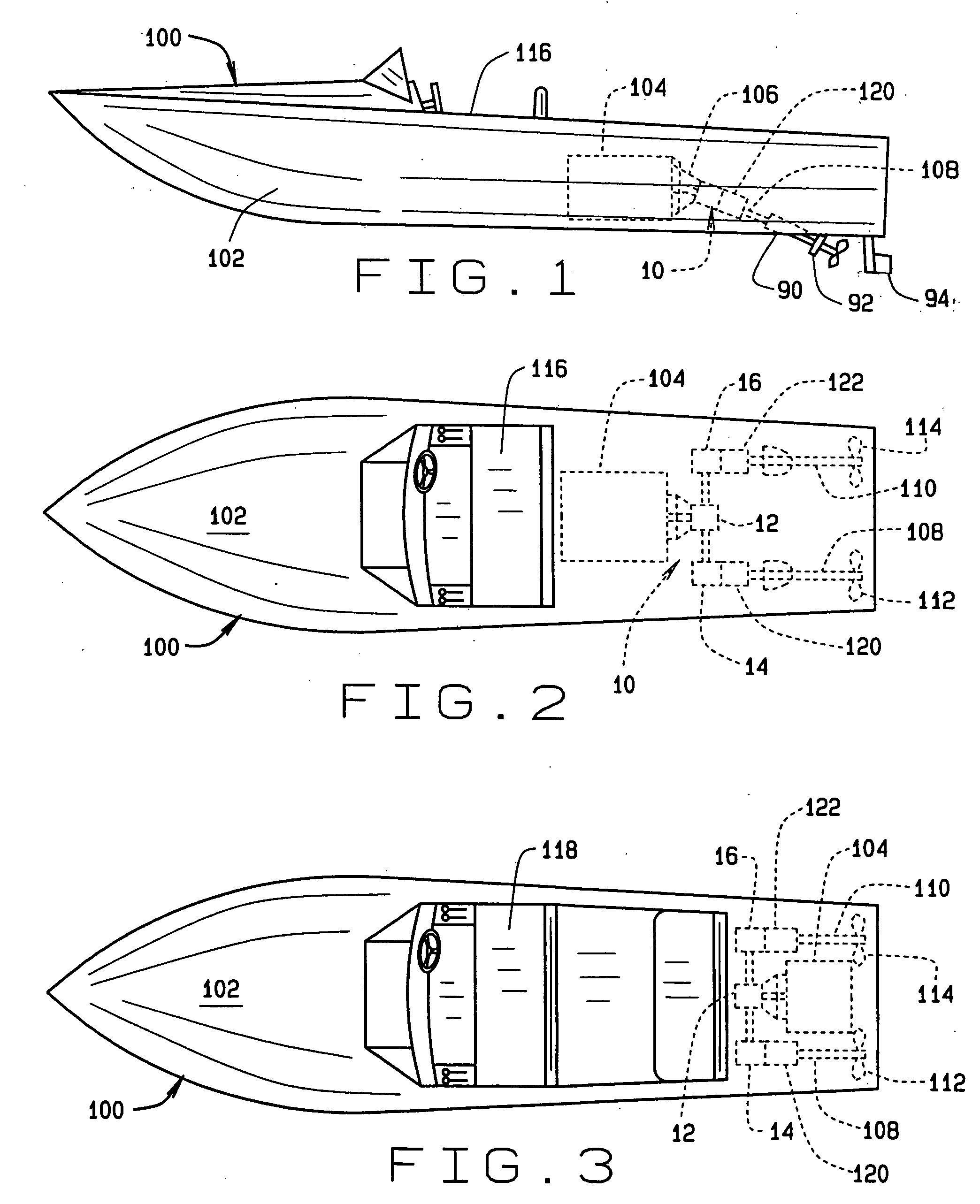
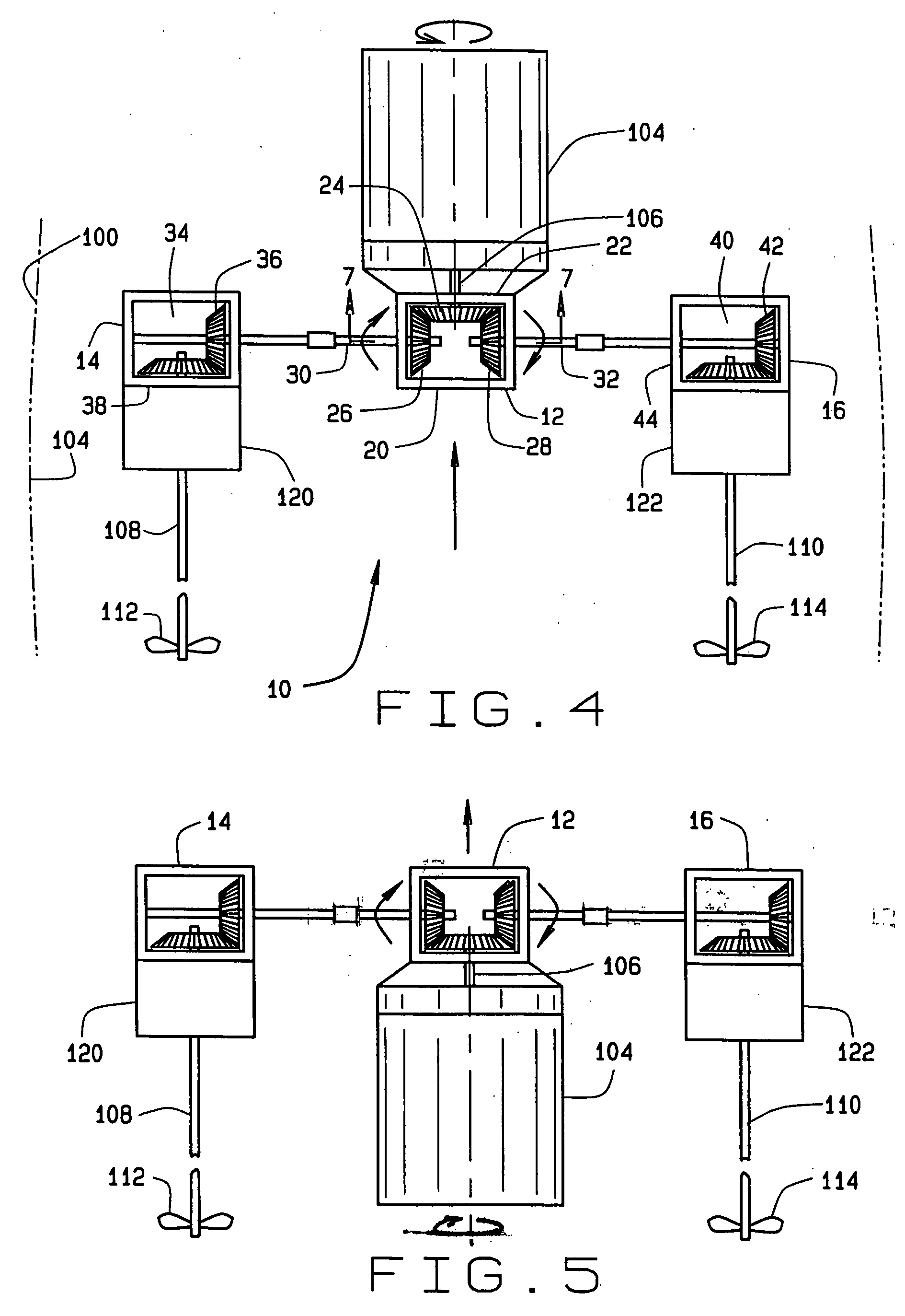
[0039] Referring now by reference numerals to the drawings and first to FIGS. 1-7 it will be understood that the drive system generally indicated by numeral 10 is used for a boat, such as the power boat indicated by numeral 100. In the embodiment shown the power boat 100 includes a hull 102, an engine 104, having a drive shaft 106; a pair of generally parallel, laterally spaced propeller shafts 108 and 110 having propellers 112 and 114, respectively.

[0040] The drive system 10 includes a primary gearbox 12 and opposed outboard gearboxes 14 and 16. The primary gearbox 12 includes a housing 20 having a U-configuration gear arrangement 22 therewithin including a bevel gear 24, attached to the engine drive shaft 106 and bevel gears 26 and 28 attached to associated elongated split shafts 30 and 32, respectively, extending between the primary gearbox 12 and outboard gearboxes 14 and 16 respectively. It will be observed that an engine adapter plate 21 facilitates the attachment of the prim...


PUM


Abstract

A boat drive system is provided for a power boat which includes an engine having a drive shaft, connected to a pair of propeller shafts. The drive system includes a primary gearbox and opposed outboard gearboxes. The primary gearbox includes a housing and a gear arrangement connected to the engine shaft and the outboard gearboxes, which are connected to the primary gearbox by a transverse shaft, include a housing and a gear arrangement connected to associated propeller shafts. A cooling system is provided including a cooling pad for each gearbox. A support system is provided for each outboard gearbox including a cradle connected to the bearing points on the hull. The engine includes an adapter plate attached to the primary gearbox for movement of the primary gearbox with the engine. In a modified drive system only one outboard gearbox is used in conjunction with a single engine. In another modified drive system a single engine and propeller are used in conjunction with a gearbox having a take-off shaft.

Description

BACKGROUND OF THE INVENTION [0001] This invention relates generally to a power boat drive system and particularly to a drive system having a superior cooling arrangement. [0002] The invention is adaptable for use with a single engine boat having a transverse drive shaft connected to twin propeller shafts. Power boats having a single engine, and twin propeller shafts are not in themselves new and are disclosed in U.S. Pat. No. 3,112,728 (Krause), U.S. Pat. No. 3,113,549 (Frank et. al), U.S. Pat. No. 3,128,742 (Cameron), U.S. Pat. No. 4,428,734 (Ludlow) and U.S. Pat. No. 6,066,012 (Nagle) which are incorporated herein by reference. Such boats have not been particularly successfully owing partly to the inadequate cooling of the drive gears and complicated mounts for the drive system. [0003] This twin drive cooling system solves these and other problems in a manner not disclosed by the known prior art. SUMMARY OF THE INVENTION [0004] This invention provides a drive system for a power bo...

Claims


Application Information

Patent Timeline
IPC IPC(8): B63H20/14
CPCB63B2770/00Y10T74/2189B63H23/06B63H5/08
Inventor CARR, RICHARD D.
Owner SUPERIOR GEAR BOX CO
Learn More