Medical instrument, in particular uretero-renoscope

a technology of ureterorenoscope and ureteral artery, which is applied in the field of medical instruments, can solve the problems risk of damage to the ureter wall, and lateral deflection and penetration into the ureter wall, so as to save space

Active Publication Date: 2006-04-27
KARL STORZ GMBH & CO KG
View PDF18 Cites 8 Cited by
  • Summary
  • Abstract
  • Description
  • Claims
  • Application Information

AI Technical Summary

Benefits of technology

[0020] For a compact design, and depending on the cross-sectional profile of the shaft, the central instrument channel can be round, or flattened in

Problems solved by technology

In practical use, it has now been found that there is a risk that instruments pushed out distally via the instrument channel may damage the wall of the ureter.
The risk o

Method used


Image

  • Medical instrument, in particular uretero-renoscope
  • Medical instrument, in particular uretero-renoscope

Examples


Embodiment Construction

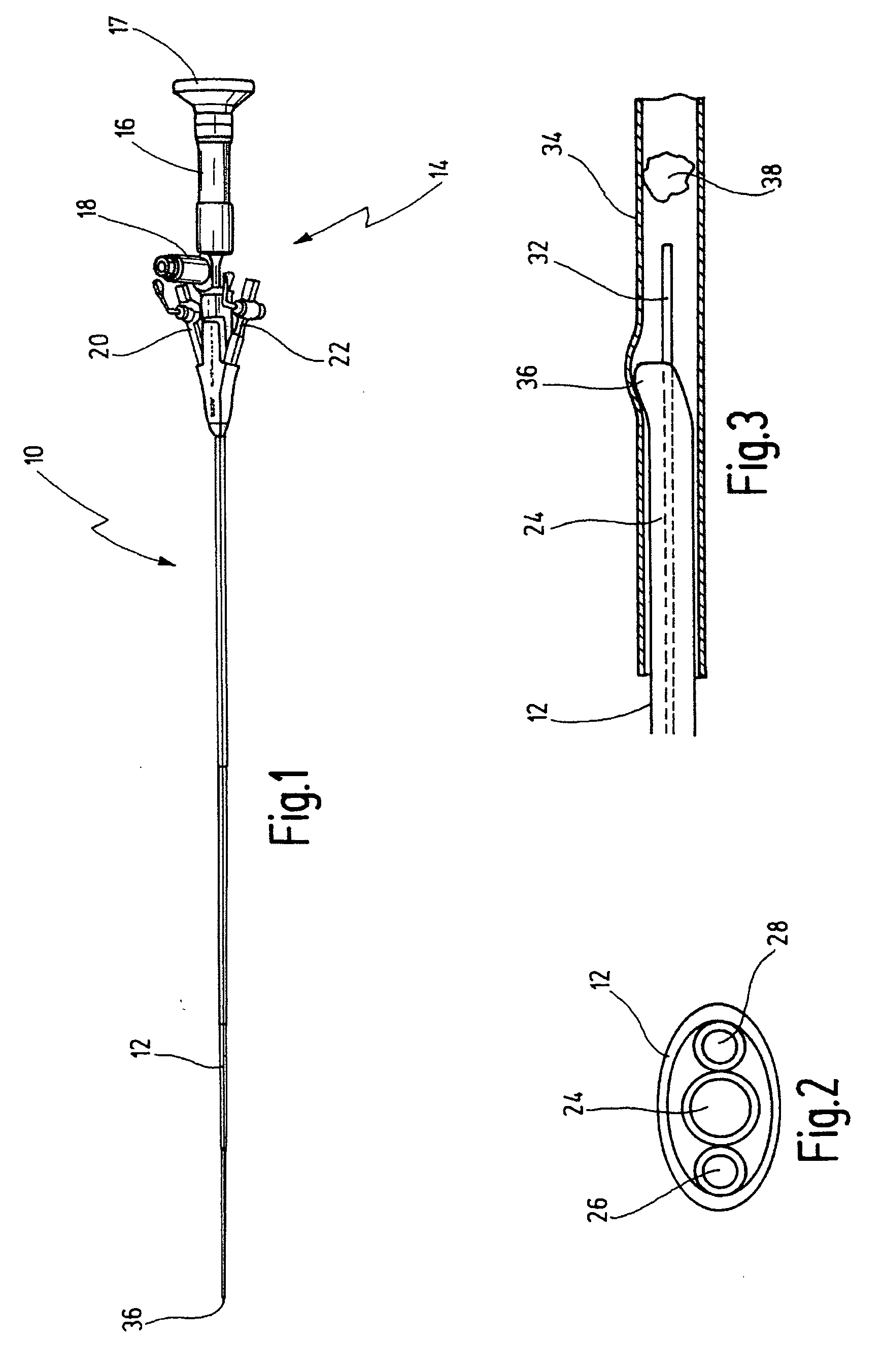
[0027] A medical instrument 10 shown in FIG. 1 is in the form of a uretero-renoscope.

[0028] The medical instrument 10 has an elongate shaft 12 and a head part 14. The head part 14 accommodates an optical system 16 which ends in an eyepiece cup 17. A light guide is attached via a lateral connector piece 18.

[0029] There are also two further connector pieces 20 and 22 which are each provided with a cock (not specifically shown here), for example for guiding irrigation fluids into the shaft 12 or for suctioning these fluids off again through the shaft 12.

[0030] The shaft 12 has a length of approximately 35 cm and a diameter of 3.5 mm.

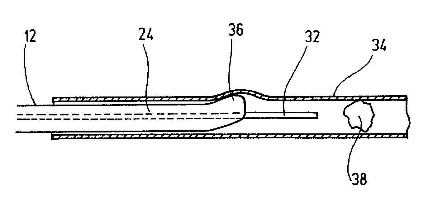
[0031] The cross section of the shaft 12 is circular along most of its length; in the distal end area the cross section is oval or flattened. From the plan view of the distal end 36 of the shaft 12 in FIG. 2, it will be seen that an instrument channel 24 is arranged centrally therein, in the present case centrally and coaxially. Alongside the central in...


PUM


Abstract

A medical instrument in particular a uretero-renoscope has a proximal head part and an elongate thin shaft for introduction into a small diameter elongate hollow organ. An instrument channel and at least one further channel is disposed within the shaft. The instrument channel is arranged centrally in the shaft.

Description

[0001] This application claims priority of German Patent Application No. 20 2004 016 621.6 filed on Oct. 25, 2004. BACKGROUND OF THE INVENTION [0002] The invention relates to a medical instrument, in particular a uretero-renoscope, with a proximal head part and with an elongate thin shaft for introduction into elongate hollow organs, in particular into a ureter. [0003] Medical instruments of this kind are known, for example, from the Applicant's catalogue “Urologie”, 7th edition, 1 / 2003, section 10 “Uretero-Renoskope”. [0004] For their application in urology, instruments of this kind are intended to be able to be inserted into hollow organs in the form of ureters. For this purpose, they have an extremely long and thin shaft, for example with a length in the region of up to 50 cm and with a diameter of 2 to 5 mm. [0005] Several channels are present in the shaft itself. One channel serves as instrument channel to allow an instrument, for example an ultrasound probe, to be conveyed thr...

Claims


Application Information

Patent Timeline
IPC IPC(8): A61B1/307A61B1/012A61B17/22A61B19/00
CPCA61B1/012A61B1/307A61B17/22012A61B19/5225A61B90/37
Inventor MICHEL, MAURICE STEPHANEISENKOLB, PETEREFINGER, ANDREAS
Owner KARL STORZ GMBH & CO KG
Why Eureka
Try Eureka