Vascular graft and deployment system

a technology of endovascular grafts and vascular grafts, which is applied in the field of vascular grafts and vascular graft deployment systems, can solve the problems of thoracic aorta being a particularly difficult environment for endovascular grafts, severe and even fatal hemorrhage, and aneurysms that may progressively expand, and achieves the effect of greater flexibility

Inactive Publication Date: 2006-04-27
DOUGLAS MYLES
View PDF33 Cites 65 Cited by
  • Summary
  • Abstract
  • Description
  • Claims
  • Application Information

AI Technical Summary

Benefits of technology

[0012] Another embodiment of the present invention comprises a catheter for delivering an endovascular device to the thoracic aorta. The catheter comprises an elongate, flexible body, having a proximal end and a distal end. An endovascular device zone is positioned on the catheter for carrying a deployable endovascular device. A flex point on the catheter is positioned within the endovascular device zone. The flex point has a greater flexibility than the elongate flexible body.

Problems solved by technology

If left untreated, the aneurysm may progressively expand until the vessel dissects or ruptures.
This may lead to severe and even fatal hemorrhaging.
As compared to, for example, the abdominal aorta artery, the thoracic aorta is a particularly difficult environment for endovascular grafts.
High pulse volumes and challenging pressure dynamics further complicate endovascular procedures.

Method used


Image

  • Vascular graft and deployment system
  • Vascular graft and deployment system
  • Vascular graft and deployment system

Examples


Embodiment Construction

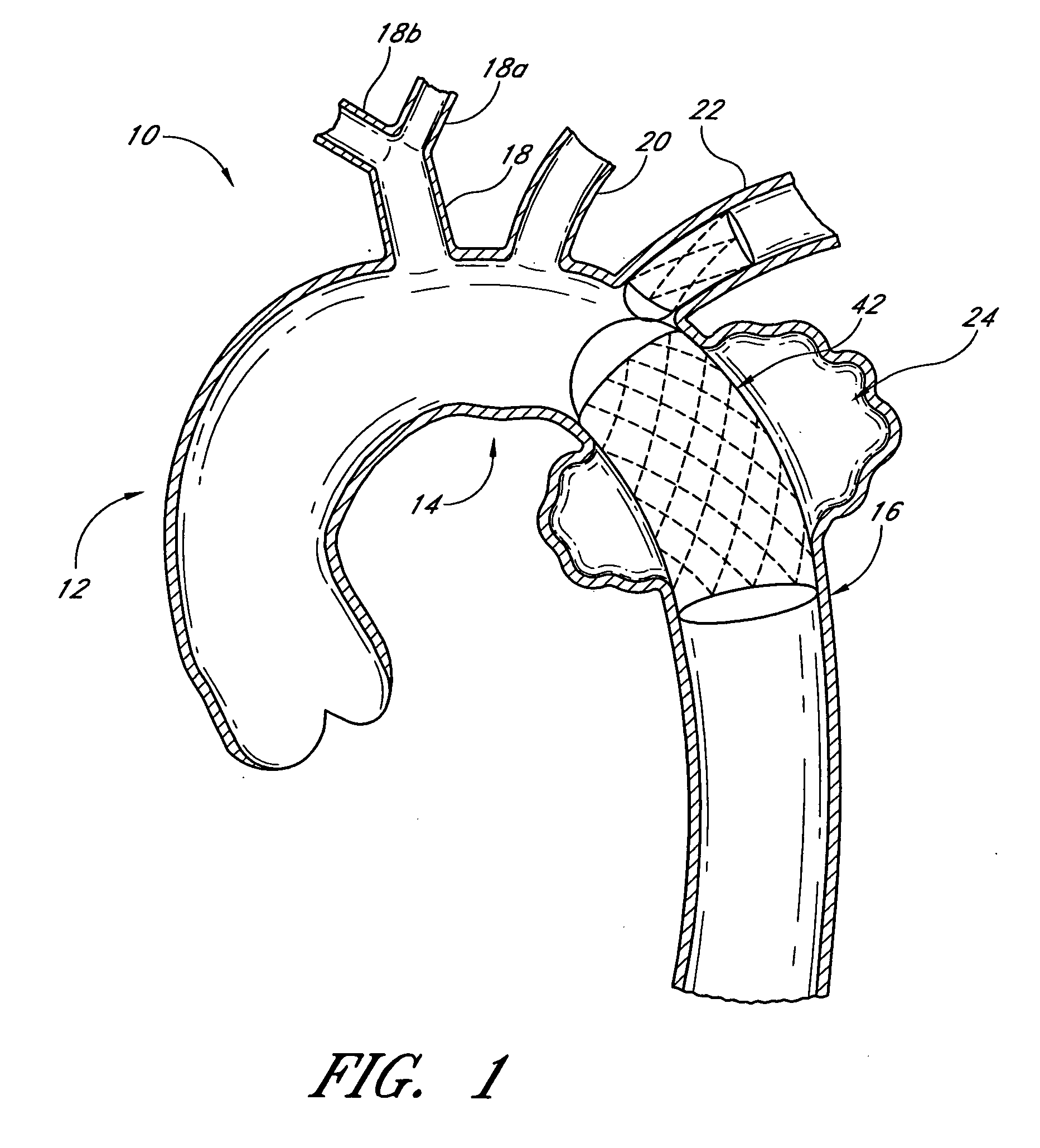
[0048]FIG. 1 illustrates a schematic representation of the thoracic aorta 10. The thoracic aorta 10 is divided into the (i) ascending aorta 12, which arises from the left ventricle of the heart, (ii) the aortic arch 14, which arches from the ascending aorta 12 and (iii) the descending aorta 16 which descends from the aortic arch 14 towards the abdominal aorta. Also shown are the principal branches of the thoracic aorta 10, which include the innomate artery 18 that immediately divides into the right carotid artery 18A and the right subclavian artery 18B, the left carotid 20 and the subclavian artery 22. An aneurysm 24 is illustrated in the descending aorta 16, just below the subclavian artery 22.

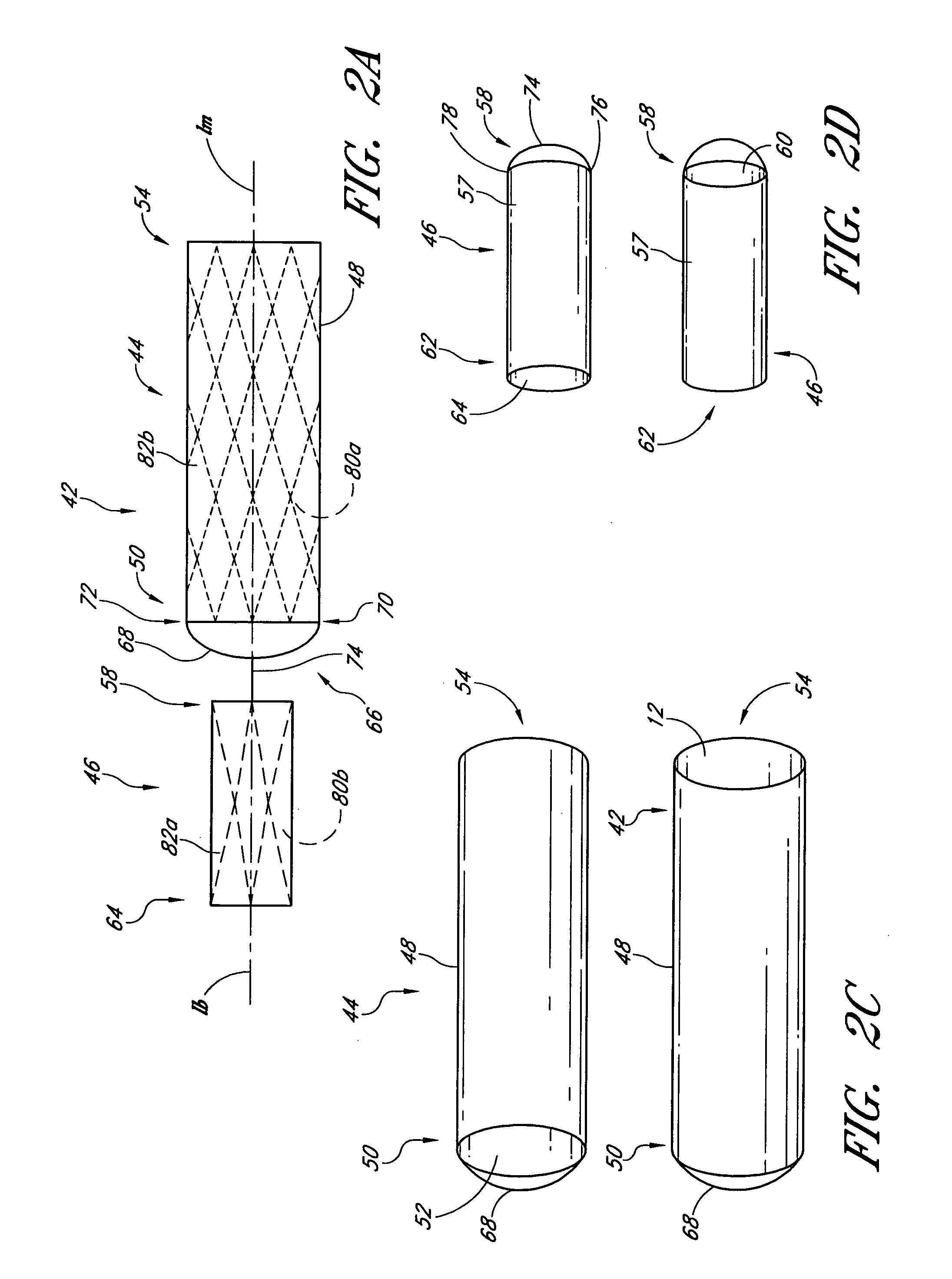
[0049]FIGS. 2A-3B illustrate an endoluminal vascular prosthesis 42, in accordance with an embodiment of the present invention. As will be explained, in more detail below, the prosthesis 42 may be used to span the aneurysm 24 as shown in FIG. 1.

[0050] With initial reference to FIGS. 2A-D, th...


PUM


Abstract

A vascular graft includes a main portion and a branch portion that is coupled to the main portion by an articulating joint. The vascular graft may be inserted into the thoracic aorta with the branch portion positioned within a branch vessel and the main portion positioned within the thoracic aorta. The graft may be deployed within a deployment apparatus comprising an outer member and an inner member. The outer member may include an area of increased flexibility that corresponds to the articulating joint.

Description

BACKGROUND OF THE INVENTION [0001] 1. Field of the Invention [0002] The present invention relates to vascular grafts and vascular graft deployment systems. [0003] 2. Description of the Related Art [0004] The aorta is the largest artery in the body and is responsible for delivering blood from the heart to the organs of the body. The aorta includes the thoracic aorta, which arises from the left ventricle of the heart, passes upward, bends over and passes down towards the thorax, and the abdominal aorta which passes through the thorax and through the abdomen to about the level of the fourth lumbar vertebra, where it divides into the two common iliac arteries. The thoracic aorta is divided into the (i) ascending aorta, which arises from the left ventricle of the heart, (ii) the aorta arch, which arches from the ascending aorta and (iii) the descending aorta which descends from the aorta arch towards the abdominal aortic. [0005] A thoracic aortic aneurysm (“TAA”) is a widening, bulge, or...

Claims


Application Information

Patent Timeline
Patent Type & Authority Applications(United States)
IPC IPC(8): A61F2/06A61F2/82
CPCA61F2/07A61F2/954A61F2/962A61F2/966A61F2002/061A61F2002/828A61F2250/0039A61F2250/006A61F2/90A61F2002/072A61F2002/075A61F2230/0054
Inventor DOUGLAS, MYLES
Owner DOUGLAS MYLES
Why Eureka
Try Eureka