Method and apparatus for reducing timing pessimism during static timing analysis

a static timing analysis and pessimism technology, applied in the field of reducing timing pessimism during static timing analysis, can solve the problems of increasing the increasing the size and complexity of integrated circuits, and needing sophisticated tools, so as to reduce timing pessimism, reduce timing pessimism, and save computational time

Active Publication Date: 2006-04-27
SYNOPSYS INC
View PDF8 Cites 19 Cited by
  • Summary
  • Abstract
  • Description
  • Claims
  • Application Information

AI Technical Summary

Benefits of technology

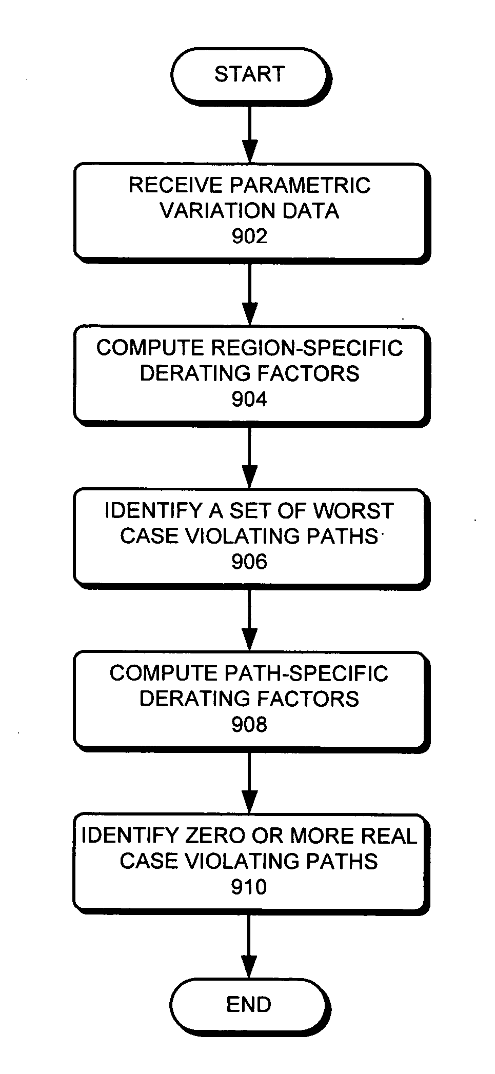
[0010] One embodiment of the present invention provides a system that reduces timing pessimism during Static Timing Analysis (STA). During operation, the system receives parametric variation data which describe the on-chip variation of timing-related parameters. Next, the system computes region-specific derating factors using the parametric variation data. The system then identifies a set of worst-case violating paths using the region-specific derating factors. Next, the system computes path-specific derating factors for one or more paths in the set of worst-case violating paths using the region-specific derating factors as well as the properties of the paths themselves (e.g., distances between their ce...

Problems solved by technology

These advances can be largely attributed to the exponential increase in the size and complexity of integrated circuits.
Due to the increase in size and complexity of integrated circuits, it has become necessary to use sophisticated tools to verify timing constraints.
As the complexity of integrated circuits grew, using simulation-based techniques to verify timing constraints became impractical because of their long runtimes, low capacities, and incomplete analyses.
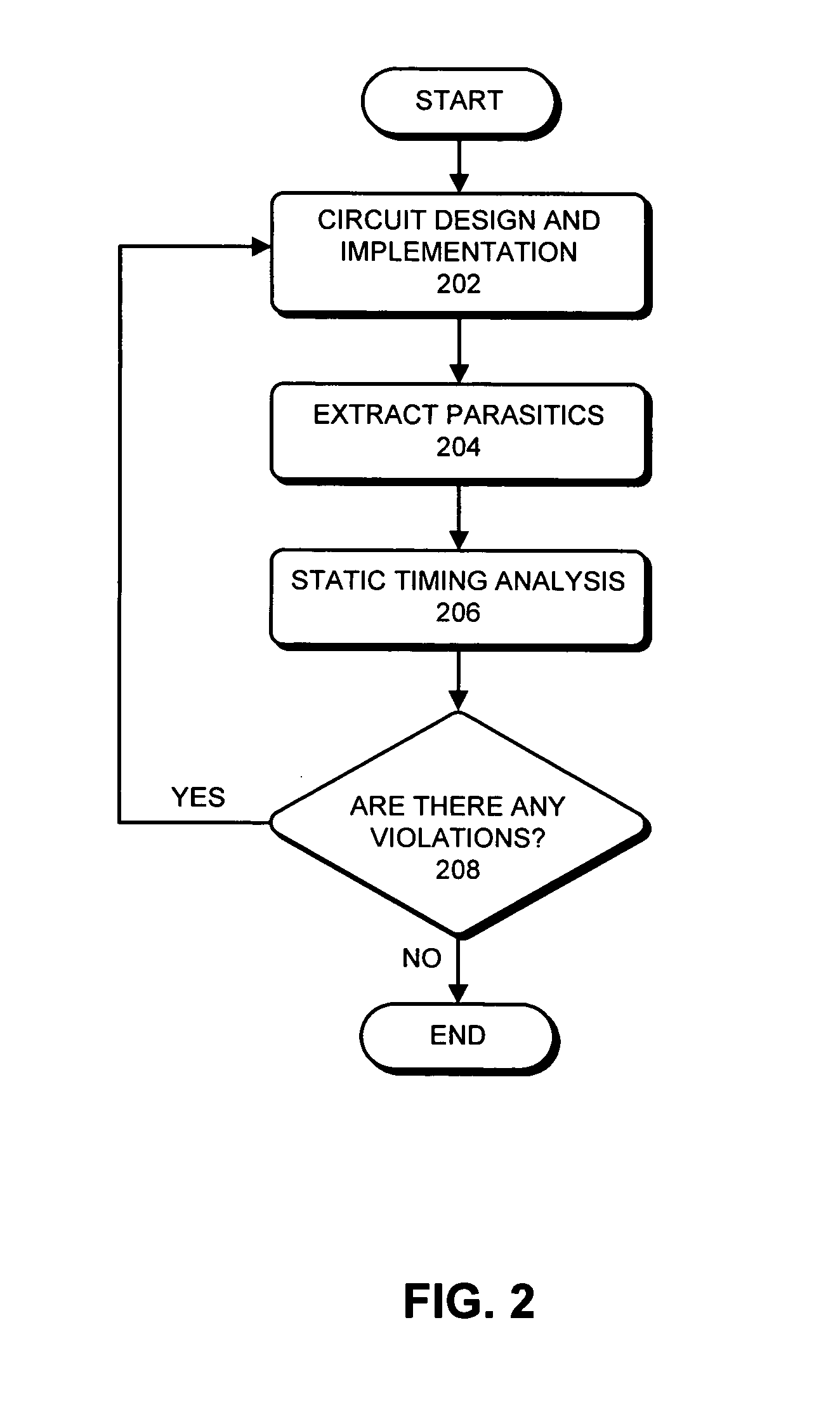
The design and fabrication of integrated circuits involve complex physical and chemical processes, which cause on-chip variation of timing-related parameters.
Consequently, present STA techniques usually solve for the worst case sce...

Method used


Image

  • Method and apparatus for reducing timing pessimism during static timing analysis
  • Method and apparatus for reducing timing pessimism during static timing analysis
  • Method and apparatus for reducing timing pessimism during static timing analysis

Examples


Embodiment Construction

Static Timing Analysis

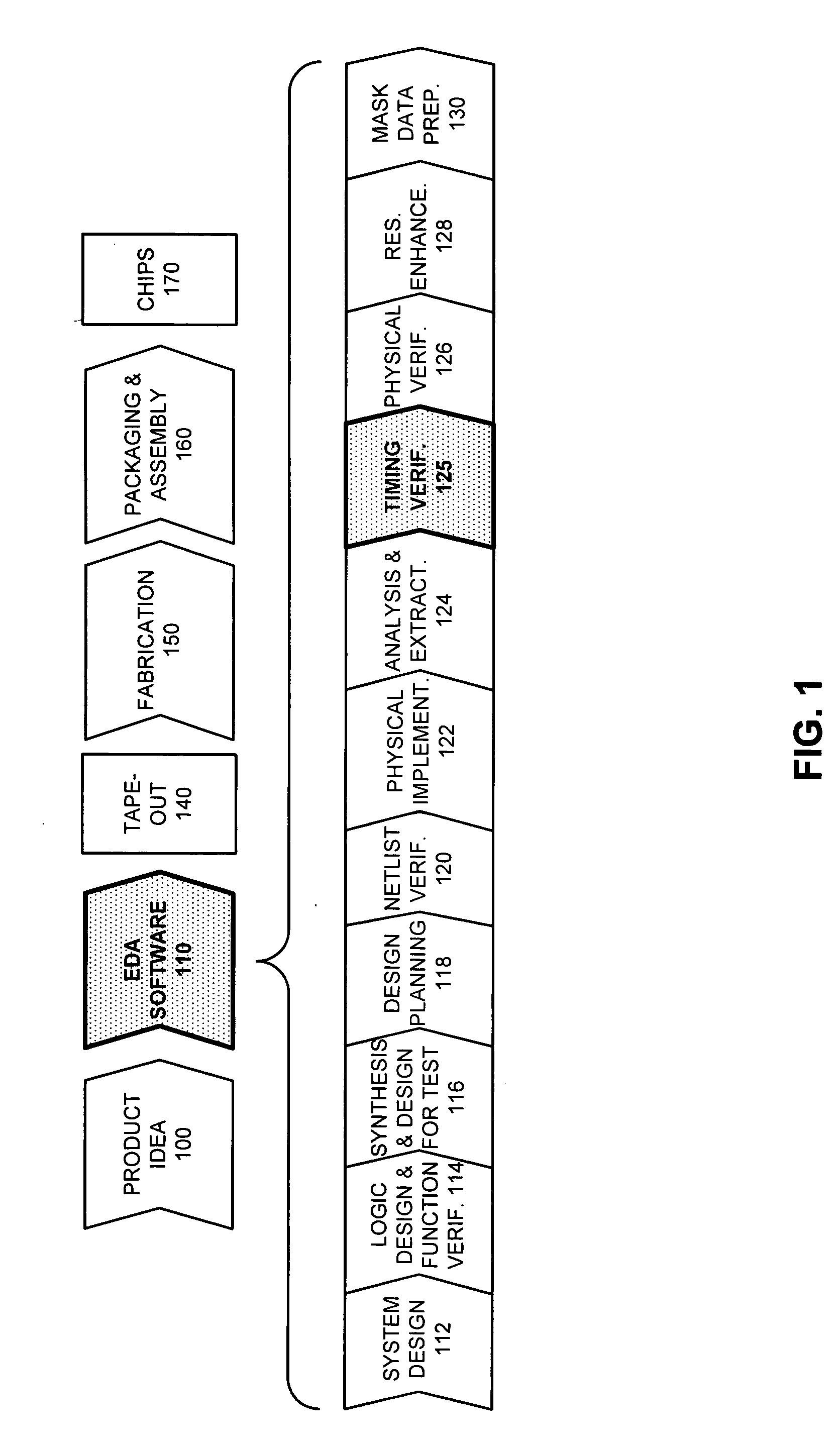
[0026]FIG. 1 illustrates the various steps in the design and fabrication of an integrated circuit in accordance with an embodiment of the present invention. The process starts with a product idea (step 100). Next, the product idea is realized by an integrated circuit, which designed using Electronic Design Automation (EDA) software (step 110). Once the design is finalized in software, it is taped-out (step 140). After tape-out, the process goes through fabrication (step 150), packaging, and assembly (step 160). The process eventually culminates with the production of chips (step 170).

[0027] The EDA software design step 110, in turn, includes a number of sub-steps, namely, system design (step 112), logic design and function verification (step 114), synthesis and design for test (step 116), design planning (step 118), netlist verification (step 120), physical implementation (step 122), analysis and extraction (step 124), timing verification (step 125), physica...


PUM


Abstract

One embodiment of the present invention provides a system that reduces timing pessimism during Static Timing Analysis (STA). During operation, the system receives parametric variation data which describes the on-chip variation of timing-related parameters. Next, the system computes region-specific derating factors using the parametric variation data. The system then identifies a set of worst-case violating paths using the region-specific derating factors. Next, the system computes path-specific derating factors for one or more paths in the set of worst-case violating paths using the parametric variation data and the path properties. Finally, the system identifies zero or more realistic-case violating paths from the set of worst-case violating paths using the path-specific derating factors.

Description

FIELD OF THE INVENTION [0001] This invention relates to the process of verifying timing constraints in an integrated circuit. More specifically, this invention relates to the process of reducing timing pessimism during static timing analysis. BACKGROUND RELATED ART [0002] Rapid advances in computing technology have made it possible to perform trillions of computational operations each second on data sets that are sometimes as large as trillions of bytes. These advances can be largely attributed to the exponential increase in the size and complexity of integrated circuits. [0003] Due to the increase in size and complexity of integrated circuits, it has become necessary to use sophisticated tools to verify timing constraints. [0004] Before the advent of Static Timing Analysis (STA), timing constraints were typically verified using simulation-based techniques. As the complexity of integrated circuits grew, using simulation-based techniques to verify timing constraints became impractica...

Claims


Application Information

Patent Timeline
IPC IPC(8): G06F17/50G06F9/45
CPCG06F17/5031G06F30/3312
Inventor KUCUKCAKAR, KAYHANDASDAN, ALI
Owner SYNOPSYS INC
Why Eureka
Try Eureka