
Thermoelectric alternators and thermoelectric climate control devices with controlled current flow for motor vehicles

a technology of motor vehicles and current flow, applied in the direction of thermoelectric device details, thermoelectric device with peltier/seeback effect, electric apparatus, etc., can solve the problem of relatively low operation efficiency of devices

Inactive Publication Date: 2006-05-04
OROBRIDGE
View PDF38 Cites 58 Cited by
  • Summary
  • Abstract
  • Description
  • Claims
  • Application Information

AI Technical Summary

Benefits of technology

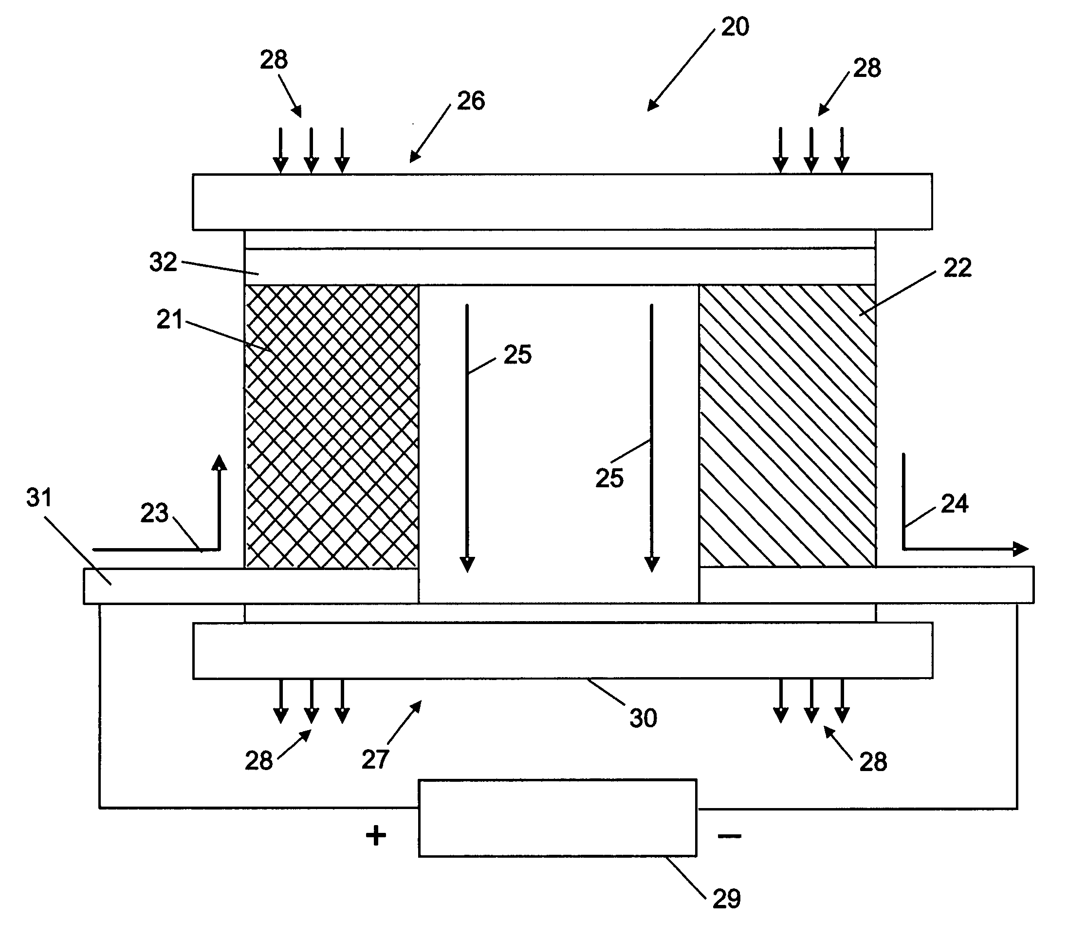
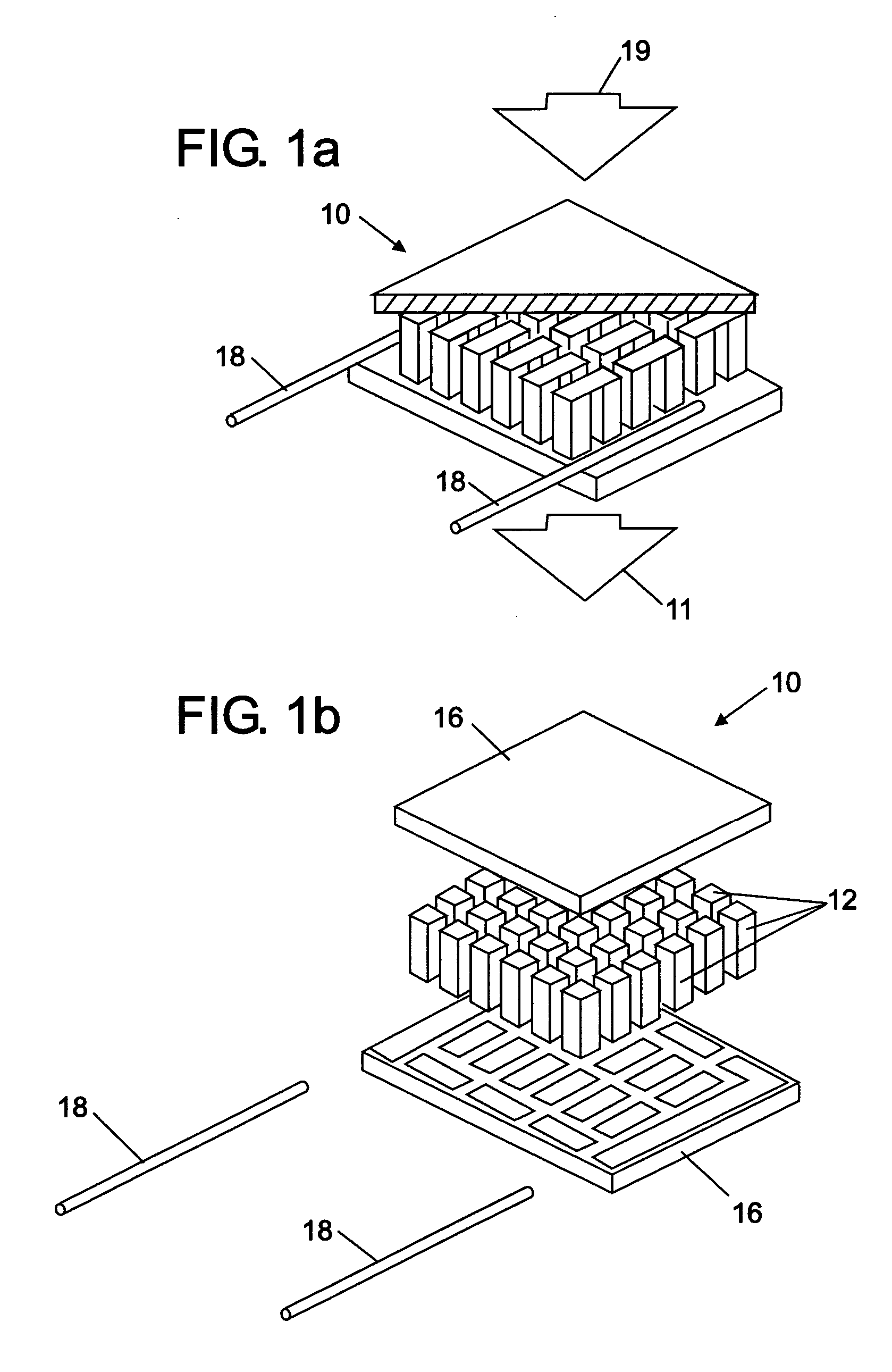
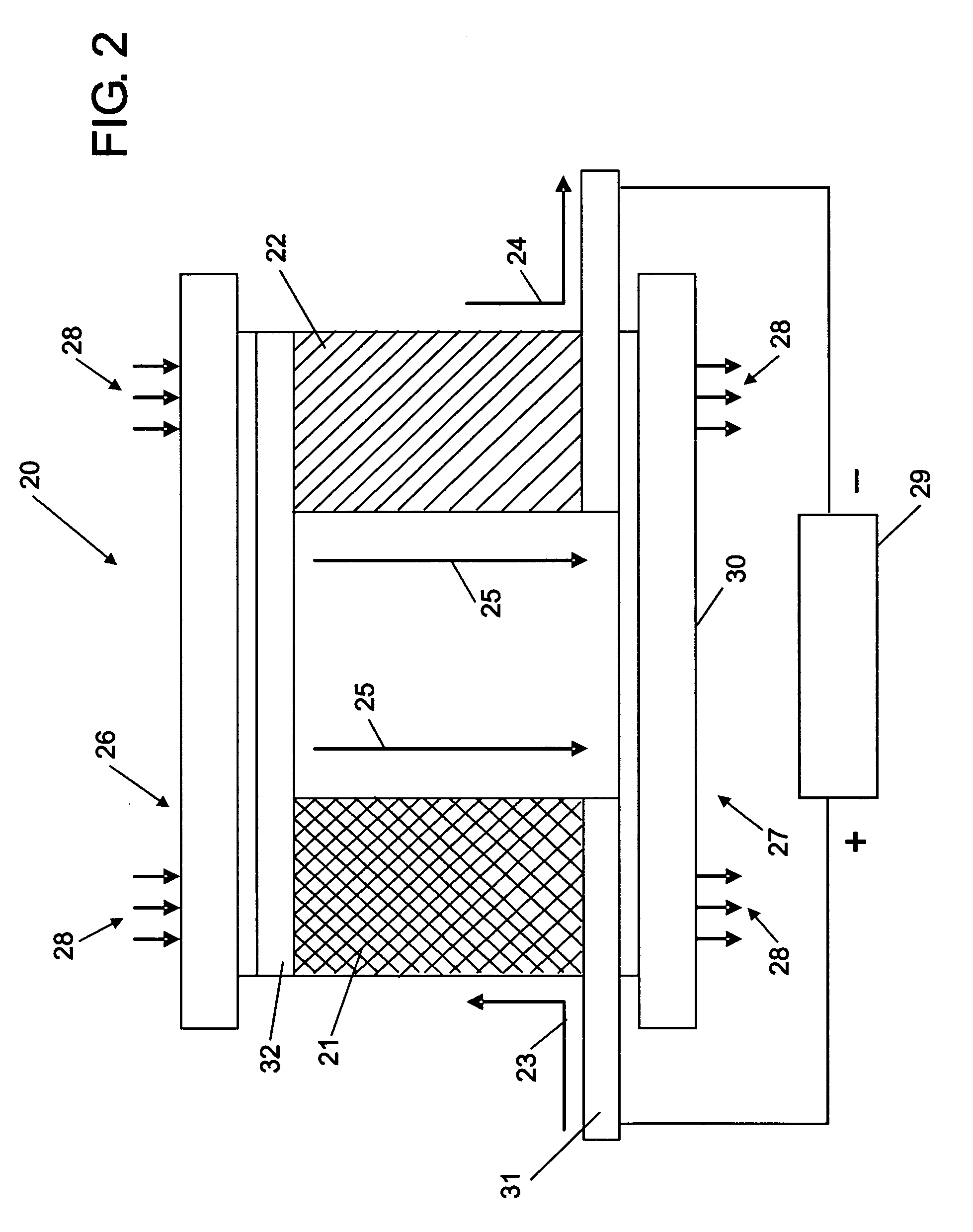
[0016] The present invention also provides thermoelectric device embodiments that can generate electrical power for a motor vehicle. Thus, a thermoelectric device embodiment with thermal energy flowing therethrough for providing electrical power to a motor vehicle is provided. For various electrical power generation embodiments, a thermoelectric device embodiment transfers thermal energy between a heat source and a heat sink from the motor vehicle and uses it to generate electrical power for the motor vehicle. The thermoelectric embodiment comprises at least a first conductive material, a first semiconductive material, a second conductive material, and a third conductive material. The first semiconductive material may be disposed adjacent to and contacting the first conductive material at a first edge thereof. Further, second conductive material can be disposed within and contacting the first semiconductive material. In addition, the third conductive material can be disposed adjacent to and contacting the first semiconductive material at a second edge thereof. One of the first conductive material and the third conductive material contains more thermal energy than the other. The effective electrical resistance between the first conductive material and the third conductive materials is controllably reduced below the effective series electrical resistance of the first semiconductive material. This can be achieved by design of the second conductive material as thermal energy flows from the first conductive material to the third conductive material. The associated Joule heating is reduced between the first conductive material and the third conductive material as thermal energy flows therebetween. Further, the Peltier cooling and Peltier heating counteract each other within the second conductive material as thermal energy flows therethrough. Thermal energy is sourced by at least the motor vehicle seeking to provide electrical power for the motor vehicle. As such, electrical energy is generated between the first conductive material and the third conductive material by the Seebeck effect due to the thermal energy transfer between the first conductive material and the third conductive material. This can generate electrical power for the motor vehicle.
[0017] In addition, a thermoelectric device embodiment with thermal energy flowing therethrough for providing electrical power to a motor vehicle is included in the present invention.

Problems solved by technology

However, these devices still have relatively low efficiencies in operation.

Method used


Image

  • Thermoelectric alternators and thermoelectric climate control devices with controlled current flow for motor vehicles
  • Thermoelectric alternators and thermoelectric climate control devices with controlled current flow for motor vehicles
  • Thermoelectric alternators and thermoelectric climate control devices with controlled current flow for motor vehicles

Examples


example manufacturing

Process Steps for Some Thermoelectric Device Embodiments

[0187] Embodiments of the present invention can be created using manufacturing methods suitable for CMOS or integrates circuit fabrication. However, other manufacturing technologies and methods, including MEMS processes, self assembly, assisted assembly, assisted self assembly, or the like can also be used to create thermoelectric device embodiments. Those skilled in the art are referred to Table 4 which describes example manufacturing process steps for some thermoelectric device embodiments according to the present invention:

TABLE 4Sample Manufacturing Process Steps* 1. Starting wafer SOI, n-type, silicon thickness = 2μ,   resistivity = 10-15 Ω-cm 2. RCA clean 3. Oxidation (20 nm) 4. Spin photoresist 5. Photolithography (define legs) 6. Wet etch oxide in 10:1 BOE 7. Reactive ion etch silicon down to SiO2 8. Strip photoresist 9. Strip oxide10. RCA clean11. Oxidation (20 nm)12. Spin photoresist13. Photolithography (define n+ r...


PUM


Abstract

Thermoelectric devices with controlled current flow are provided for motor vehicle applications including but not limited to electrical power generation applications such as thermoelectric alternators, alternator supplements, generators, and battery chargers. Further, thermoelectric devices with controlled current flow are provided for other motor vehicle climate control applications such as air conditioning, cooling, heating, and refrigeration. Thermoelectric devices and systems are disposed between heat sources and heat sinks of a motor vehicle, or between hot surfaces and cooler surfaces of a motor vehicle. For power generation applications, thermoelectric devices convert the temperature gradient between a heat source and a heat sink into electrical energy for the motor vehicle. For climate control applications, thermoelectric devices are driven by electrical current such that thermal energy is transferred between a heat source and a heat sink to provide heating, cooling, or both. Methods related to the above are also provided.

Description

CROSS REFERENCE TO RELATED APPLICATIONS [0001] This patent application claims the benefit of U.S. provisional application Ser. No. 60 / 608,329 filed Sep. 9, 2004, the entire contents of which are incorporated by reference herein. Further, this patent application claims the benefit of U.S. provisional application Ser. No. 60 / 622,776 filed Oct. 28, 2004, the entire contents of which are incorporated by reference herein. In addition, this patent application is a Continuation-in-Part (“CIP”) of U.S. patent application Ser. No. 11 / 223,735 filed on Sep. 9, 2005, the entire contents of which are incorporated by reference herein and from which priority benefits are claimed. Lastly, this patent application is a Continuation-in-Part (“CIP”) of PCT patent application serial number PCT / US05 / 32292 filed on Sep. 9, 2005, the entire contents of which are incorporated by reference herein and from which priority benefits are claimed.FIELD OF THE INVENTION [0002] The present invention generally relate...

Claims


Application Information

Patent Timeline
IPC IPC(8): H01L35/30H01L35/28
CPCH01L35/04H01L35/32H10N10/81H10N10/17
Inventor ONVURAL, O. RAIF
Owner OROBRIDGE
Learn More