
RF supply system and plasma processing apparatus

a technology of supply system and plasma processing device, which is applied in the direction of electrical apparatus, electric discharge tube, basic electric elements, etc., can solve the problems of flexibility in size and location of matching units, etc., and achieve the effect of improving rf supply efficiency and reducing transmission loss and heat generation

Active Publication Date: 2006-05-04
TOKYO ELECTRON LTD
View PDF6 Cites 8 Cited by
  • Summary
  • Abstract
  • Description
  • Claims
  • Application Information

AI Technical Summary

Benefits of technology

[0009] An object of the present invention is to provide an RF supply system and plasma processing apparatus, which can reduce transmission loss and heat generation, so as to remarkably improve the RF supply efficiency.
[0010] Another object of the present invention is to provide an RF supply system and plasma processing apparatus, which can reduce the volume and size of a matching unit typically formed as a matching box, and increase the flexibility of location of the matching unit.

Problems solved by technology

One of the problems concerns transmission loss and heat generation in supplying an RF power.
Another problem concerns flexibility in the size and location of the matching unit.
A further problem concerns flexibility in the design of the RF generation mechanism on the process chamber side, in accordance with increase in the diameter of the process chamber.

Method used


Image

  • RF supply system and plasma processing apparatus
  • RF supply system and plasma processing apparatus

Examples


Embodiment Construction

[0031] In the process of developing the present invention, the inventors studied conventional plasma processing apparatuses and RF supply sections thereof, such as those shown in FIG. 4. As a result, the inventors have arrived at the findings given below.

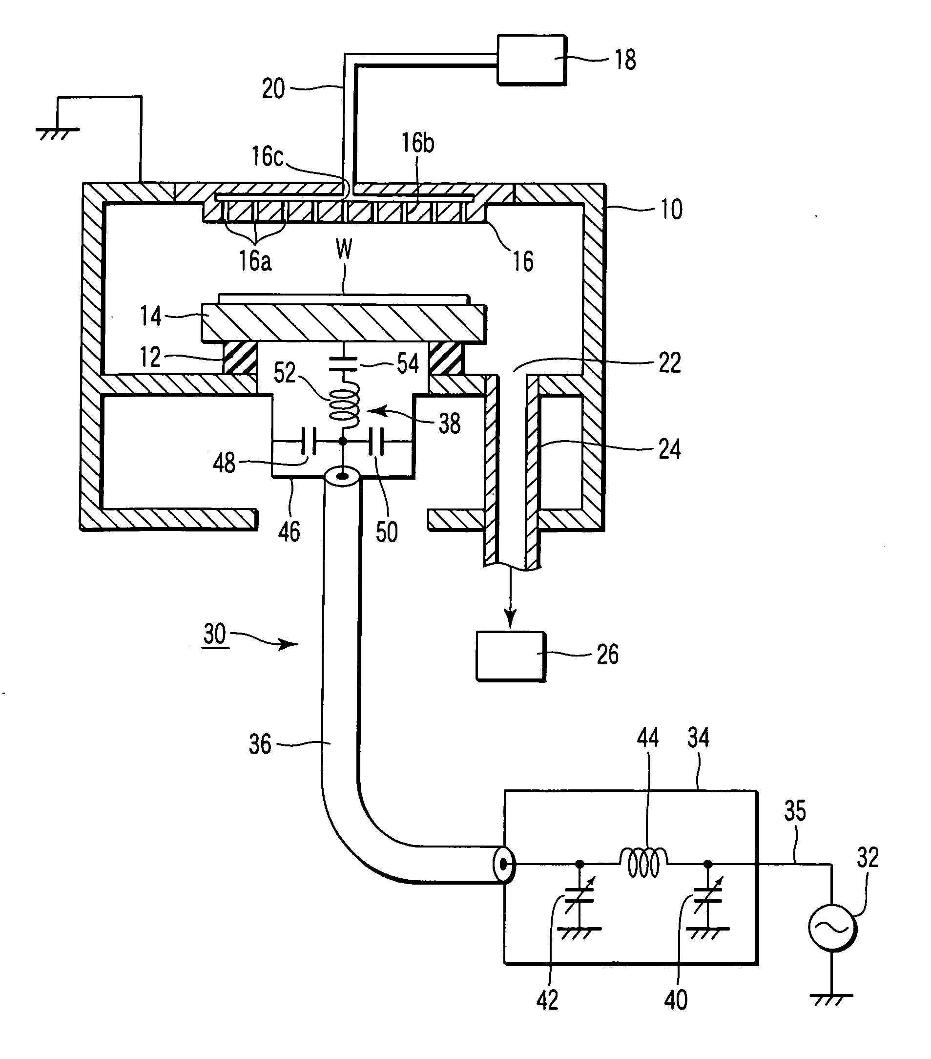
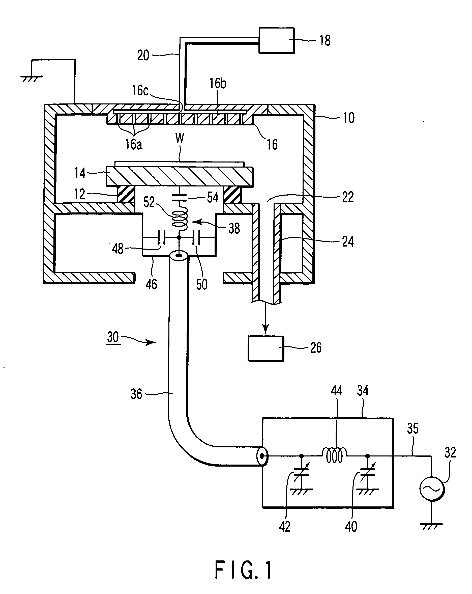
[0032]FIG. 5 is a view for explaining an operation of the RF supply section shown in FIG. 4. When an RF power is supplied from the RF supply section 106 to the lower electrode 104 inside the process chamber 100, plasma PZ of a process gas is generated in the space between the upper electrode 102 and lower electrode 104. Viewing from the RF supply section 106, the lower electrode 104, plasma PZ, upper electrode 102, and process chamber 100 are connected in series and form an integrated load (which will be referred to as “process chamber load” hereinafter). An RF primary current i1 flows between the RF power supply 114 and matching unit 116, and an RF secondary current i2 flows between the matching unit 116 and process chamber load. ...


PUM

PropertyMeasurementUnit
frequencyaaaaaaaaaa
diameteraaaaaaaaaa
transmission impedance rSaaaaaaaaaa

Abstract

An RF supply system is to be connected to an RF electrode disposed outside or inside a process chamber to assist a plasma process performed in the process chamber. This system includes an RF power supply, a matching unit, and an impedance converter. The RF power supply is configured to supply an RF power for plasma generation to the electrode through a transmission path. The matching unit is disposed on the transmission path between the RF power supply and the electrode, and configured to match a load impedance viewing from the RF power supply with an impedance of the RF power supply side. The impedance converter is disposed on the transmission path between the matching unit and the electrode, and configured to convert a load impedance viewing from the matching unit to an impedance higher than an actual impedance on the electrode side.

Description

CROSS-REFERENCE TO RELATED APPLICATIONS [0001] This application is based upon and claims the benefit of priority from prior Japanese Patent Application No. 2004-319634, filed Nov. 2, 2004, the entire contents of which are incorporated herein by reference. BACKGROUND OF THE INVENTION [0002] 1. Field of the Invention [0003] The present invention relates to an RF (Radio Frequency) supply system for supplying an RF power for plasma generation, and a plasma processing apparatus using the system. For example, the plasma processing apparatus is used for performing a plasma process on a target substrate in a semiconductor processing system. The term “semiconductor process” used herein includes various kinds of processes which are performed to manufacture a semiconductor device or a structure having wiring layers, electrodes, and the like to be connected to a semiconductor device, on a target substrate, such as a semiconductor wafer or a glass substrate used for an LCD (Liquid Crystal Displa...

Claims


Application Information

Patent Timeline
Patent Type & Authority Applications(United States)
IPC IPC(8): C23F1/00
CPCC03C15/00H01J37/32082H01J37/32183
Inventor SATO, KENJI
Owner TOKYO ELECTRON LTD
Learn More