Controller for wire electric discharge machine
- Summary
- Abstract
- Description
- Claims
- Application Information
AI Technical Summary
Benefits of technology
Problems solved by technology
Method used
Image
Examples
Embodiment Construction
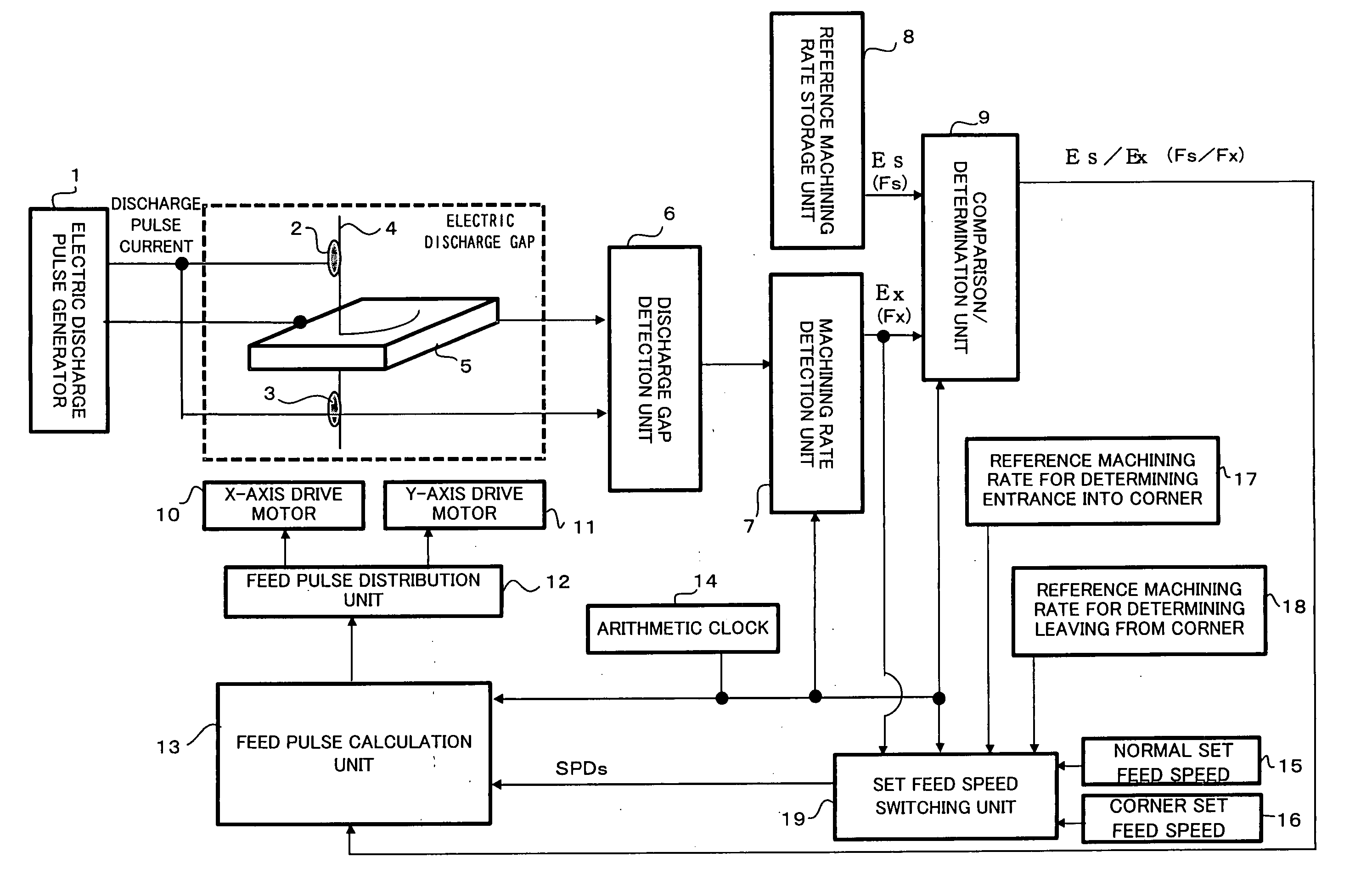
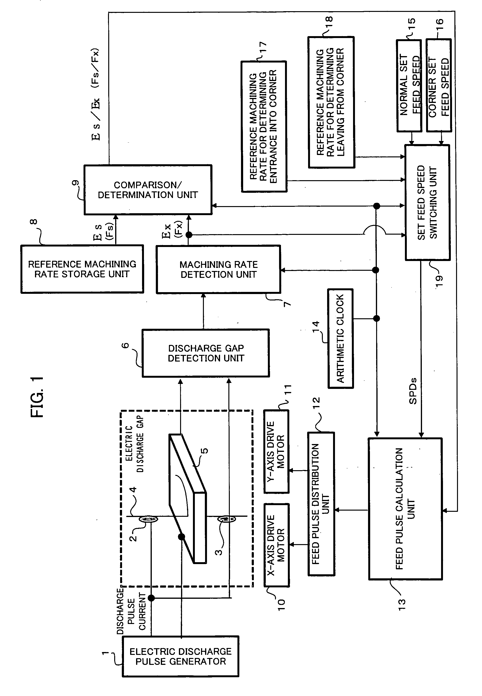
[0048]FIG. 1 is a block diagram showing relevant parts of a controller for a wire electric discharge machine in one embodiment of this invention. An electric discharge pulse generator 1 is for applying an electric discharge pulse voltage across a gap between a wire electrode 4 and a workpiece 5 for electric discharge machining, and comprises a direct-current power source, a circuit including a switching element such as a transistor, a capacitor charging / discharging circuit, etc. Conducting brushes 2 and 3 are for transmitting electricity to the wire electrode 4, and connected to one of the terminals of the electric discharge pulse generator 1. The workpiece 5 is connected to the other terminal of the electric discharge pulse generator 1. The electric discharge pulse generator 1 applies a pulse voltage between the traveling wire electrode 4 and the workpiece 5. A table (not shown) on which the workpiece 5 is mounted is driven by an X-axis drive motor control device 10, a Y-axis drive...
PUM
| Property | Measurement | Unit |
|---|---|---|
| Speed | aaaaa | aaaaa |
| Electric potential / voltage | aaaaa | aaaaa |
| Threshold limit | aaaaa | aaaaa |
Abstract
Description
Claims
Application Information
 - R&D
- Intellectual Property
- Life Sciences
- Materials
- Tech Scout
- Unparalleled Data Quality
- Higher Quality Content
- 60% Fewer Hallucinations
Browse by: Latest US Patents, China's latest patents, Technical Efficacy Thesaurus, Application Domain, Technology Topic, Popular Technical Reports.
© 2025 PatSnap. All rights reserved.Legal|Privacy policy|Modern Slavery Act Transparency Statement|Sitemap|About US| Contact US: help@patsnap.com


