Aligned composite structures for mitigation of impact damage and resistance to wear in dynamic environments

a composite structure and dynamic environment technology, applied in the field of fibrous monolith composites, can solve the problems of unpredicted, catastrophic failure, controlled failure of the structure, etc., and achieve the effects of increasing flaw insensitivity, increasing wear resistance, and improving mechanical properties

Inactive Publication Date: 2006-05-04
ADVANCED CERAMICS
View PDF29 Cites 18 Cited by
  • Summary
  • Abstract
  • Description
  • Claims
  • Application Information

AI Technical Summary

Benefits of technology

[0012] The present invention relates to structures that include unique architectural arrangements of fibrous monolith (“FM”) composites to provide the structures with enhanced mechanical properties, including increased flaw insensitivity, increased wear resistance, and damage tolerance. The present invention also relates to methods of fabricating such composites and structures.
[0013] Fibrous monoliths are a unique class of structural materials that have mechanical properties similar to continuous fiber reinforced ceramic composites (“CFCCs”). Such properties include relatively high fracture energies, damage tolerance, and graceful failures, as well as chemical inertness and thermal shock resistance. In contrast to CFCCs, however, FMs can be produced at a significantly lower cost. FMs, which include ceramics and / or other metals, generally may be manufactured by powder processing techniques using inexpensive ceramic or metal powders or combinations thereof. As a result of the high performance characteristics of FMs and the low costs of manufacture, FMs can be used in a wider range of applications than heretofore typical for monolithic ceramic composites.
[0014] The composite materials of the present invention may be used as coatings for existing structures to mitigate impact damage in dynamic environments and to reduce wear on the structures, as the composites demonstrate very high fracture energies, increased flaw insensitivity, increased wear resistance, and increased damage tolerance. The composite materials also may provide a renewable coating material having superior wear and lubricating characteristics for surfaces of ball bearings, wear parts, such as cutting tool inserts and, round tools, including drills, endmills and routers, and the like where it is desired to include a lubricating material to further reduce wear. In other aspects, a more substantial portion of, or even a complete, structure may be formed from the FM composites, thereby extending the benefits obtained with use of the FM composites.
[0015] Generally, FM composites include one or more filaments having at least a core material and a shell material, which generally are selected from diamond, graphite, ceramic oxides, ceramic carbides, ceramic nitrides, ceramic borides, ceramic silicides, ceramic phosphates, metals, metal alloys, intermetallics and combinations thereof. A plurality of filaments may be bundled together one or more times to provide a final filament that includes a plurality of core and shell phases of reduced diameters. An FM composite may include a plurality of core phases maintained in spaced separation by one or more shell phases. Such arrangements inter alia result in controlled failure of the structure to avoid unpredicted, catastrophic failures. The core phases of the FM composites, which typically provide structural strength and hardness, may include ceramic, carbide and metallic materials. The shell phase(s) typically enhances the toughness of the composite structure by creating pressure zones, microcrack zones, ductile-phase zones, and / or weak debond-type interfaces. These weak interfaces between the discrete core phases are intended to deflect cracks and to delaminate, thereby limiting brittle failure of the FM composite.
[0016] In other embodiments as referenced above, at least one of a core or shell material of the FM composite includes a lubricious composition to further reduce wear associated with high cutting and contact forces. The lubricious composition may be selected to enhance wear resistance as well as the cosmetic attributes of the composite structure. A plurality of filaments having a lubricious shell composition may be bundled together to provide a predetermined amount of the lubricating composition at the wear surface. In other aspects, a monolithic structure having a wear surface includes a lubricious composition contained within the monolithic structure to provide a predetermined amount of the lubricious composition at the wear surface at any time during the life of the structure. The structures are fabricated so that a predetermined amount of the lubricious composition is available at the wear surface even as the surface is worn down by use. The lubricious composition essentially serves as a renewable lubricating coating for the wear surface during the life of the structure.

Problems solved by technology

Such arrangements inter alia result in controlled failure of the structure to avoid unpredicted, catastrophic failures.

Method used


Image

  • Aligned composite structures for mitigation of impact damage and resistance to wear in dynamic environments
  • Aligned composite structures for mitigation of impact damage and resistance to wear in dynamic environments
  • Aligned composite structures for mitigation of impact damage and resistance to wear in dynamic environments

Examples


example 1

[0078] The thermoplastic / powder blends are produced in batches and are formulated on a volumetric basis. One blend includes between about 50 to about 62 vol. % of ceramic powder, between about 37 to about 50 vol. % of thermoplastics, and between about 0 to about 12 vol. % of plasticizers. The mass of a batch of ceramic / thermoplastic dope varies with the density of the ceramic powder. A batch of Si3N4 has a density of about 3.44 g / cc and produces approximately 1 kg of “green” compound material.

example 2

[0079] Initial damage resistant testing was conducted on a FM composite consisting of a cellular diamond material surrounded by a ductile metal phase of WC—Co (FIG. 4a). Impact drop tests demonstrated that the FM composite remained undamaged at much higher drop heights as compared to a standard monolithic diamond material.

example 3

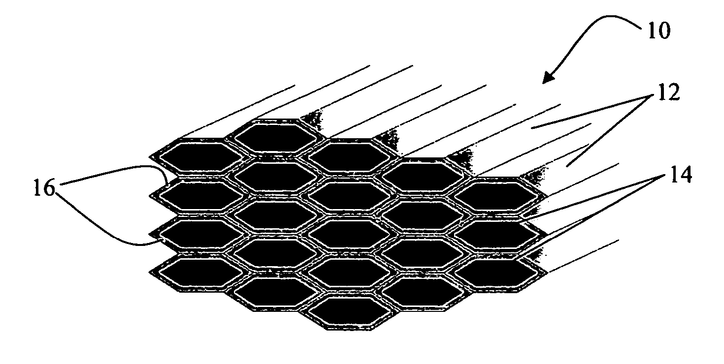
[0080] Composites having unique architectures were produced by fabricating Si3N4 / BN FM layers and hot pressing the layers into different Si3N4-based substrates. Three different sets of Si3N4 were fabricated for testing. The three billets fabricated were: 1) a Si3N4 / BN FM layer on a monolithic Si3N4 substrate, 2) a Si3N4 / BN FM layer on a unidirectional Si3N4 / BN FM substrate, and 3) a Si3N4 / BN FM layer on a quasiisotropic Si3N4 / BN FM substrate.

[0081] These samples were fabricated using a two-step process. First, the Si3N4 / BN FM layer was produced. Specifically, a unidirectional Si3N4 / BN billet (3″×4.5″×0.5″) was laminated using multiple, extruded Si3N4 / BN filaments. The individual cell size was approximately 200 μm. Thin 0.12 inch FM layers were produced by sectioning the billet into thin 0.12 inch slices along its width to expose the cells. Each 0.12 inch slice constituted a FM layer.

[0082] Second, the monolithic, uniaxial, and quasiisotropic FM substrates were processed. For the m...


PUM

PropertyMeasurementUnit
thicknessesaaaaaaaaaa
temperaturesaaaaaaaaaa

Abstract

Fibrous monolith composites having architectures that provide increased flaw insensitivity, improved hardness, wear resistance and damage tolerance and methods of manufacture thereof are provided for use in dynamic environments to mitigate impact damage and increase wear resistance.

Description

CROSS-REFERENCE TO RELATED APPLICATIONS [0001] This application is a divisional of U.S. patent application Ser. No. 10 / 310,594 filed Dec. 4, 2002, which is a continuation-in-part of U.S. patent application Ser. No. 10 / 005,084, filed Dec. 4, 2001. This application also is based on, and claims the benefit of, U.S. Provisional Application No. 60 / 251,172, filed on Dec. 4, 2000, and entitled “Aligned Fibrous Monolith Constructs for Mitigation of Foreign Object Damage in Dynamic Environments.” The specifications of these applications are incorporated herein by reference.[0002] This invention was made with U.S. Government support under grants DE-FC02-96CH10861 and DE-FC26-01NT41051 awarded by the Department of Energy. Accordingly, the Government may have certain rights in the invention described herein.FIELD OF THE INVENTION [0003] The present invention relates to fibrous monolith composites that provide increased flaw insensitivity, improved hardness, wear resistance, and damage tolerance...

Claims


Application Information

Patent Timeline
Patent Type & Authority Applications(United States)
IPC IPC(8): D01D5/34B32B3/26D21H13/00B28B5/00C04B33/36C04B35/64C08K3/34C08K7/04
CPCB32B3/26Y10T428/24149B32B2315/02C04B35/117C04B35/62865C04B35/62868C04B35/645C04B35/806C04B2235/3843C04B2235/524C04B2235/5264C04B2235/6021C04B2237/368C04B2237/38C08K3/34C08K7/04C04B2235/6567C04B2235/658C04B2237/34C04B2237/341C04B2237/343C04B2237/363C04B2237/704C04B2237/76Y10T428/24926B32B18/00C04B35/80Y10T428/249953Y10T428/249964Y10T428/249965Y10T428/24998Y10T428/31504Y10T442/2615Y10T442/2623
Inventor MULLIGAN, ANTHONY C.RIGALI, MARK J.SUTARIA, MANISH P.POPOVICH, DRAGANHALLORAN, JOSEPH P.FULCHER, MICHAEL L.COOK, RANDY C.
Owner ADVANCED CERAMICS
Why Eureka
Try Eureka